Mechanical installation
42/14-37 EN
Thermal Mass Flowmeter FMT200-D (Sensyflow D)
15
Please observe the following points valid for all pipe diameters:
1. Observe the pipeline wall thickness and amount of shrinkage when welding!
2. Rectangularity to the pipe axis must be absolutely kept (max. tolerance: 2°).
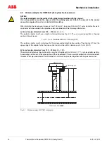
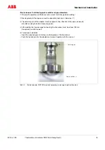
3. The centering pin of the adapter must be aligned in flow direction to the pipe axis exactly
(at outlet run length, behind measuring point).
4. After welding the free passage for inserting the transducer must be at least 28 mm
(if required, use drill to clear).
5. Transducer installation
– Insert the supplied gasket into the provided groove of the transducer.
– Push the transducer into the adapter and screw it together with the cap-nut.
Bild 4-2
Weld-on adapter DIN11851 mounted to pipeline, centering pin right (outflow side)
Flow direction
→
Centering pin

