Mounting and installation
42/14-36 EN
Thermal Mass Flowmeter FMT400-VTS, FMT400-VTCS (Sensyflow VT-S/VT-CS)
25
Hygienic version with FG flange
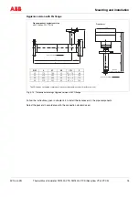
Fig. 4-14
Dimensional drawings Hygienic version with FG flange
Follow the instructions given in chapter 4.4 to install the transducers in the pipe components.
Select the gaskets in accordance with the connection standard used.
Pipe component, hygienic version
with FG flange: FG 1, PN10
Transducer
DN
L
L1
L2
∅
D
F
25
175
133
42
29
×
1,5
83
40
270
205
65
42
×
2
100
50
330
265
65
54
×
2
110
80
510
425
85
85
×
2
142
The FG flanges on the pipe component’s process side are always smooth (without groove).
Ø D
L1
L
L2
120
F
Direction of flow
125
58
77
120
255
Centre
of pipe component
Direction of flow

