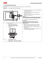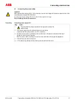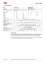
Technical Data
32
Thermal Mass Flowmeter FMT400-VTS, FMT400-VTCS (Sensyflow VT-S/VT-CS)
42/14-36 EN
Type
FMT400-VTS (Sensyflow VT-S)
FMT400-VTCS (Sensyflow VT-CS)
Operating conditions
Recommended
inlet and outlet runs
acc. to DIN EN ISO 5167-1
min. inlet 15
×
D, outlet 5
×
D
Environmental conditions
Ambient temperature
Connection head
-25...+70 °C
Storage temperature
-25...+85 °C
Process conditions
Operating temperature medium
(transducer)
Ceramic sensor: -25...+300°C
Metal sensor: -25...+250°C
-25...+150 °C
Operating pressure (max.)
40
×
10
5
Pa (40 bar)
16
×
10
5
Pa (16 bar) pipe fitting S
(for DN 80: 10
×
10
5
Pa (10 bar))
10
×
10
5
Pa (10 bar) FG flange
Pressure loss
(logarithmic diagram)
< 1.0 kPa (10 mbar), typical value 0.1 kPa (1 mbar)
Mechanical construction
Design/dimensions/weight
dependent on nominal size
dependent on nominal size
Material (standard)
1.4571, Ceramics
stainless steel e.g. 1.4301
Process connection (standard)
Flange acc. to EN 1092-1 form B1, PN 40 or
ANSI B 16.5 150/300 lbs
Pipe fitting S acc. to DIN 11851
or FG flange
Components
– VTS transducer
– VT pipe component design 1 or 2
or weld-on adapter
VTCS transducer
VTC pipe component
Standard nominal pipe sizes
Pipe component design 1: Wafer flange
DN 40, 50, 80, 100, 150, 200 –
ANSI 1½“, 2“, 3“, 4“, 6“, 8“
Pipe component design 2: measuring section
DN 25, 40, 50 – ANSI 1“, 1½“, 2“
Weld-on adapter for square ducts
or pipe sizes
≥
DN 150
Pipe component hygienic version: measuring section
DN 25, 40, 50, 80
Type of protection
IP 65
Auxilary energy
Electrical power supply
Voltage
Power consumption
Current drain
24 V DC
±
25 %; 24 V AC
±
25 %, 48...62 Hz
< 15 W
< 600 mA, slow-blow fuse of at least 2 A recommended
Cable entry
M20 x 1.5
10
50
100
500
1000
5000 10000
10
5
0,5
0,1
1
DN 50
DN 80
DN 100
DN 150
Z-18927
DN 25
Pressure drop (mbar)
Mass flow rate (kg/h)

