Mounting and installation
14
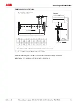
Thermal Mass Flowmeter FMT400-VTS, FMT400-VTCS (Sensyflow VT-S/VT-CS)
42/14-36 EN
4.4
Installation
CAUTION
Safety instructions
When dismounting, with more than 1.1 bar absolute pressure, or with high temperatures or health-
hazardous gases in the pipe, the use of the exchange tool is recommended and obligatory for safety rea-
sons
(see chapter 4.7).
Non-observance may lead to severe injuries of persons.
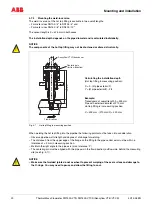
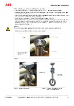
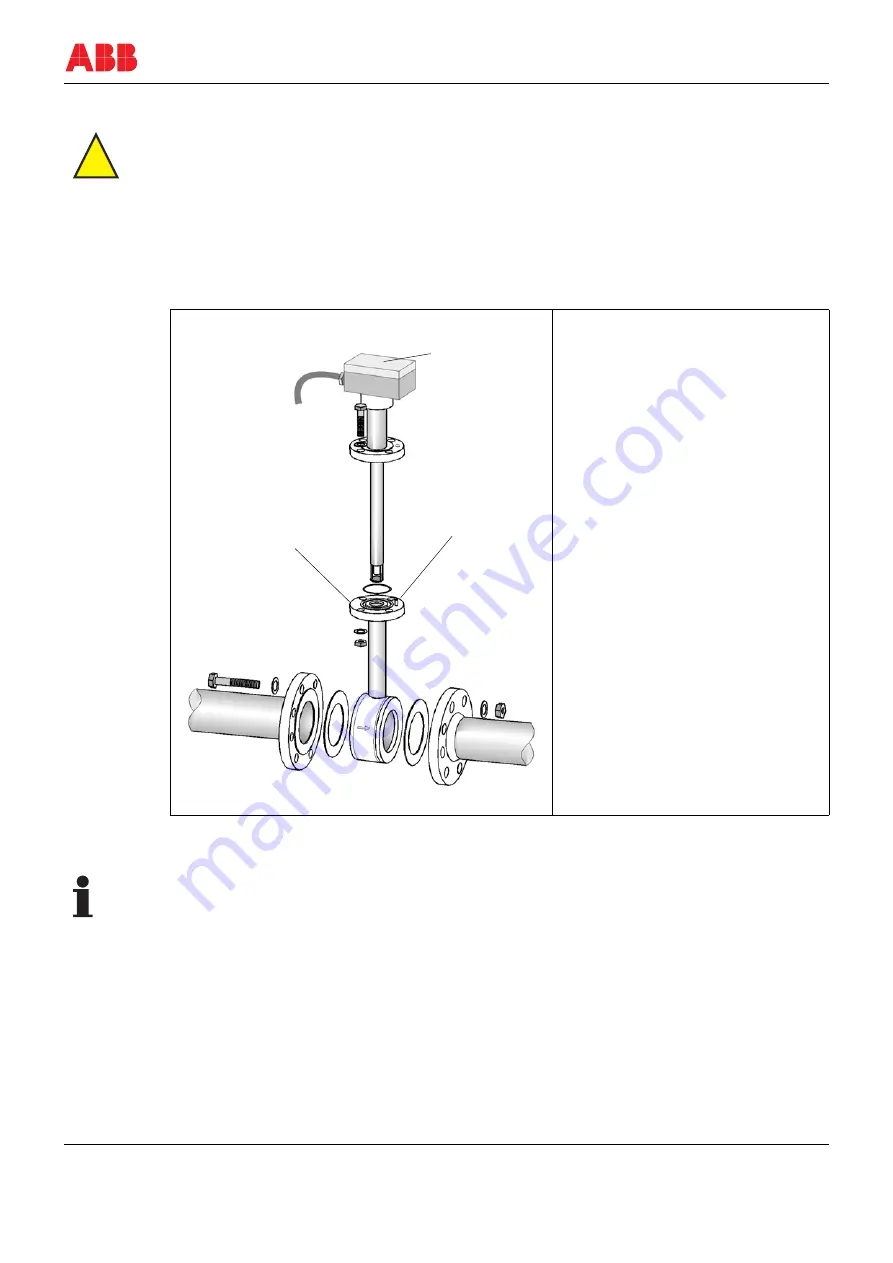
The installation is described using the example of a pipe component of type 1 in intermediate flange version. The
description analogously also applies to a type 2 pipe component and the weld-on adapters.
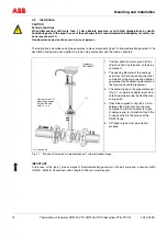
Fig. 4-1
Schematic illustration of a pipe component 1 with intermediate flange
IMPORTANT
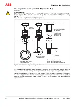
In the case of the type 1 pipe component (intermediate flange version) with ball valve and a nominal width
DN 200 / ANSI 8", transducers with a length of 425 mm must be used.
!
(1) Centering pin
1.
The flow direction must agree with the
direction shown by the arrow on the pipe
component.
2.
The opening diameter of the sealings
used may not be changed and should on
completion of the component installation
guarantee that the detecting element and
the pipe are absolutely leakproof.
3.
The centering pin on the pipe component
(Fig. 4-1) or weld-on adapter must be lo-
cated downstream side (behind the mea-
suring point).
4.
Check the supplied O-ring (55 x 3 mm)
between the transducer and the pipe
component / weld-on adapter for signs
of damage prior to installation. Insert the
O-ring exactly into the groove of the
DN 25 flange.
5.
All flange screws must be installed
properly.
(1)
Pipe component 1 in
wafer flange design
DN 40 to DN 200
ANSI 1½“ to 8“
Transducer
FMT400-VTS

