background image

— 

A B B   M E A S U R E M E N T   &   A N A L Y T I C S   |   O P E R A T I N G   I N S T R U C T I O N    

Sensyflow FMT500-IG 

Thermal Mass Flowmeter


— 
ABB Limited 
Measurement & Analytics 

Howard Road, St. Neots 
Cambridgeshire, PE19 8EU 
UK 
Tel:  +44 (0)870 600 6122 
Fax:  +44 (0)1480 213 339 
Email: enquiries.mp.uk@gb.abb.com 

ABB Automation Products GmbH 
Measurement & Analytics 

Schillerstr. 72 
32425 Minden 
Germany 
Tel:   +49 571 830-0 
Fax:  +49 571 830-1806 

abb.com/flow


ABB Inc. 
Measurement & Analytics 

125 E. County Line Road 
Warminster, PA 18974 
USA 
Tel:  +1 215 674 6000 
Fax:  +1 215 674 7183 


For gas, intelligent analog / HART 
PROFIBUS DPV1  

Measurement made easy 

OI

/F

M

T500-I

G

-E

N Re

v. C 

03

.2

019


— 
Sensyflow FMT500-IG 

Introduction 

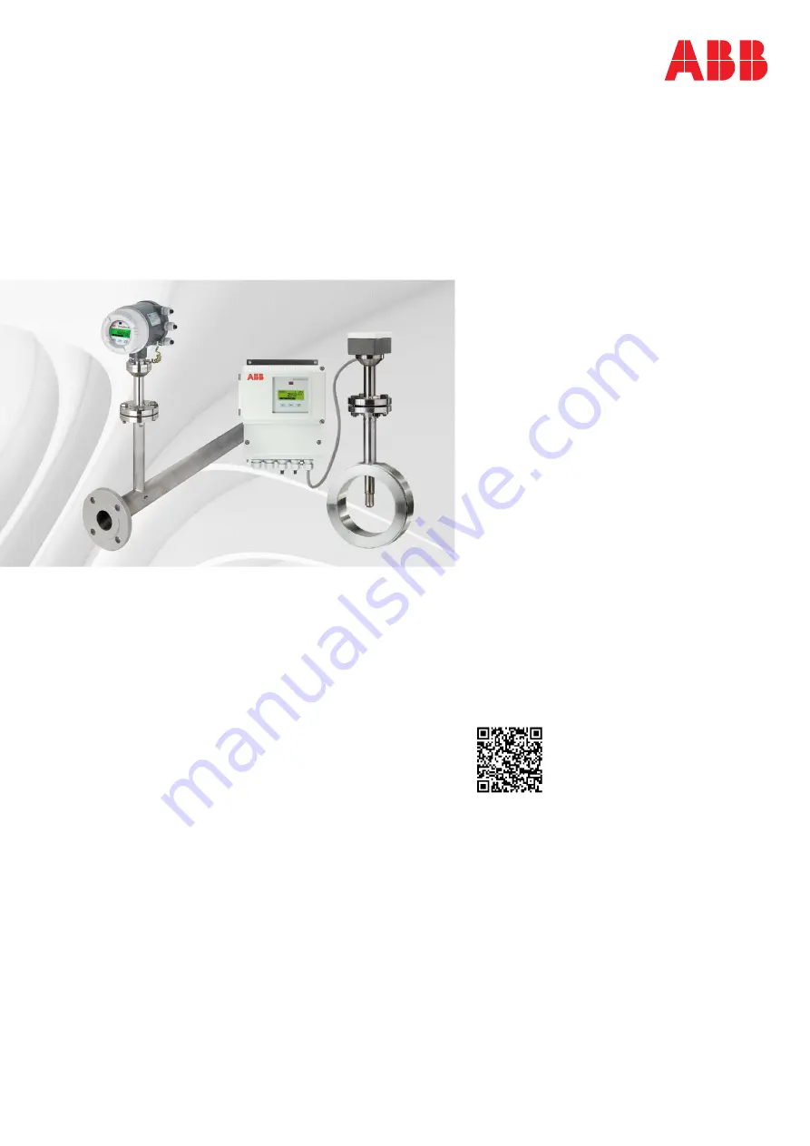
The Sensyflow FMT500-IG thermal mass 
flowmeter is a digital mass flowmeter for air, gas 
and gas mixtures in process applications. The 
measuring system is equipped with a LCD 
display, integrated gas temperature 
measurement and counter functions.  

Additional Information 

Additional documentation on  
Sensyflow FMT500-IG is available for download free 
of charge at www.abb.com/flow. 
Alternatively simply scan this code: 

— 
We reserve the right to make technical changes or modify the contents of this document 
without prior notice. With regard to purchase orders, the agreed particulars shall prevail.  
ABB does not accept any responsibility whatsoever for potential errors or possible lack of 
information in this document.  

We reserve all rights in this document and in the subject matter and illustrations contained 
therein. Any reproduction, disclosure to third parties or utilization of its contents – in whole 
or in parts – is forbidden without prior written consent of ABB. 

© ABB 2019 

3KXF421008R4201 


Summary of Contents for Sensyflow FMT500-IG

Page 1: ...syflow FMT500 IG thermal mass flowmeter is a digital mass flowmeter for air gas and gas mixtures in process applications The measuring system is equipped with a LCD display integrated gas temperature measurement and counter functions Additional Information Additional documentation on Sensyflow FMT500 IG is available for download free of charge at www abb com flow Alternatively simply scan this cod...

Page 2: ...25 Minden Germany Tel 49 571 830 0 Fax 49 571 830 1806 Customer service center Phone 49 180 5 222 580 automation service de abb com Copyright 2019 by ABB Automation Products GmbH Subject to changes without notice This document is protected by copyright It assists the user in safe and efficient operation of the device The contents of this document whether whole or in part may not be copied or repro...

Page 3: ... DIN EN ISO 5167 1 15 4 2 Installing the flowmeter sensor and pipe components 16 4 3 Weld on adapter for Sensyflow FMT500 IG 17 4 4 Weld on adapter with ball valve for Sensyflow FMT500 IG 18 4 5 Integrated hot tap fitting for Sensyflow FMT500 IG 20 4 5 1 Specifications for integrated hot tap fittings 21 4 5 2 Installing the wafer version 21 4 5 3 Installing the weld in version 22 4 5 4 Installing ...

Page 4: ... Parameter changes 48 11 Ex relevant specifications 50 11 1 Zone 2 22 version 50 11 1 1 Marking 50 11 1 2 Safety specifications for inputs and outputs 50 11 2 Designs for potentially explosive atmospheres in accordance with ATEX and FM 50 11 2 1 Options regarding installation in potentially explosive atmospheres 51 11 2 2 ATEX Marking 51 11 2 3 Temperature table for ATEX designs 52 11 2 4 FM desig...

Page 5: ...roduct is built based on state of the art technology and is operationally safe It has been tested and left the factory in perfect working order from a safety perspective The information in the manual must be observed and followed in order to maintain this state throughout the period of operation Modifications and repairs to the product may only be performed if expressly permitted by these instruct...

Page 6: ...ng to pressure and temperature as stated on the name plate in the operating instructions must not be exceeded When installing and disassembling pipe components or flowmeter sensors ensure that the pipeline has been depressurized Exception If you are using a hot tap fitting Before carrying out installation work on pipelines used to carry aggressive or toxic measuring media media that may be classed...

Page 7: ...t specifications It is very important to use the O ring supplied not a flat gasket This is resistant to measuring media and should be inserted in the groove provided in the pipe component flange Take care not to damage the measuring elements when inserting the flowmeter sensor into the pipe component as this is not permitted The flowmeter sensor should be firmly bolted together with the flange of ...

Page 8: ...rmation may result in death or severe injury WARNING Bodily injury This symbol in conjunction with the signal word Warning indicates a potential electrical hazard Failure to observe this safety information may result in death or severe injury CAUTION Minor injury This symbol in conjunction with the signal word Caution indicates a possibly dangerous situation Failure to observe this safety informat...

Page 9: ...r supply 10 Maximum power 11 Protection class 12 Permissible ambient temperature 13 Measured medium temperature 1 5 2 Transmitter with remote mount design Fig 2 1 Manufacturer 2 Manufacturing number 3 Internal type designation 4 Serial Number 5 Hardware Level 6 ID number internal calibration number 7 Explosion protection labeling e g ATEX 8 Year of manufacture country of manufacture 9 Full type de...

Page 10: ...cture 9 Full type designation 10 IP rating 11 Permissible ambient temperature 12 Measuring medium temperature 1 5 4 Integral mount design Fig 4 1 Manufacturer 2 Manufacturing number 3 Internal type designation 4 Serial Number 5 Hardware Level 6 ID number internal calibration number 7 Explosion protection labeling e g ATEX 8 Year of manufacture country of manufacture 9 Full type designation 10 Powe...

Page 11: ...riginal packaging or a secure transport container of an appropriate type if you need to return the device for repair or recalibration purposes Fill out the return form see the Appendix and include this with the device The EU Directive governing hazardous materials dictates that the owners of any hazardous waste are also responsible for disposing of it All devices delivered to the manufacturer must...

Page 12: ...We conduct an open dialog with the public through our publications 1 9 Disposal This product is manufactured from materials that can be reused by specialist recycling companies 1 9 1 Information on WEEE Directive 2012 19 EU Waste Electrical and Electronic Equipment This product is not subject to WEEE Directive 2012 19 EU or relevant national laws e g ElektroG in Germany The product must be dispose...

Page 13: ...ctions All parts must be installed in accordance with the manufacturer s specifications as well as relevant standards and regulations Commissioning and operation must comply with EN 60079 14 Electrical apparatus for explosive gas atmospheres 2 1 Approvals Data relating to the approvals for use in potentially explosive atmospheres can be found in the chapter Ex relevant specification 2 2 Ex relevan...

Page 14: ... 1 1 2 8 Integrated hot tap fitting in wafer type design DN 50 DN 200 ASME 2 8 Not approved for use in a potentially explosive atmosphere Type 2 pipe component as a measuring section DN 25 DN 80 ASME 1 2 Weld on adapter DN 100 ASME 4 and above Weld on adapter with ball valve DN 100 ASME 4 and above Not approved for use in a potentially explosive atmosphere Fig 5 1 Centering pin outflow side 2 FMT5...

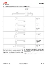
Page 15: ...ces e g valve and reducer you must always consider the longer inlet run length In confined spaces at the mounting location the outlet run length can be shortened to 3 x D The reduction of the minimum inlet run length however will impact on the achievable accuracy High repeatability of the measuring value is still provided Under certain circumstances special calibration can be performed for insuf f...

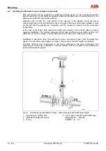
Page 16: ...ipe component wafer type design care must be taken to ensure centered installation The internal diameters of the pipe and flange must match exactly Any differences in levels or edges or untidy weld seams will reduce the measuring accuracy Installation is described using the example of a pipe component of type 1 with the wafer type design The description also applies to a type 2 pipe component and ...

Page 17: ...rs or non circular cable cross sections you must observe the following points when attaching the weld on adapter to the pipeline 1 The length of the weld on adapter must be equal to L once it has been welded on see Figures 7 and 8 L h 1 2 x Ø Dexternal where h 263 mm 10 35 inches 425 mm 16 73 inches or 775 mm 30 51 inches flowmeter sensor lengths Shorten the length of the weld on adapter as approp...

Page 18: ...nto account for calibration IMPORTANT NOTE Deviations from the stated dimension and position tolerances cause additional measuring uncertainty 4 4 Weld on adapter with ball valve for Sensyflow FMT500 IG Versions featuring a ball valve enable the flowmeter sensor to be installed and disassembled at low gauge pressures in the pipeline with minimal gas leakage Install the weld on adapter as described...

Page 19: ...ctive cage or the sensor elements Do not close the ball valve until the flowmeter sensor has been removed Direction of flow Fig 8 Dimensions in mm inch 1 Centering pin 2 Sealing ring groove 3 Connection flange DN 25 1 D Outer pipe diameter Flowmeter sensor length h in mm inch Outer pipe diameter min max in mm inch 263 10 35 100 150 3 94 5 91 425 16 73 150 500 5 91 19 69 775 30 51 500 1150 19 69 45...

Page 20: ... 6 Sensor elements Flowmeter sensor length h Water flange version Weld in version h 263 mm 10 35 for DN 50 DN 65 and DN 80 2 3 h 425 mm 16 73 for DN 100 DN 125 DN 150 and DN 200 4 6 8 h always 425 mm 16 73 If you want to be able to remove the sensor during actual operation without gas escaping the integrated hot tap fitting should be used instead of the pipe components and weld on adapter We recom...

Page 21: ... lengths see Fig 9 Temperature Max 200 C 392 F Pressure abs 16 bar 90 C 232 psi 194 F 1 bar 200 C 14 5 psi 392 F Fig 10 Maximum pressure temperature values for integrated hot tap fitting 4 5 2 Installing the wafer version Fig 11 left shows the installed wafer version of the hot tap fitting in the disassembly position The guide tube is in its upper end position and seals the Sensyflow opening right...

Page 22: ...vidually WARNING Do not shorten hot tap fitting components or interfere with the design This can lead to the measuring medium escaping in an uncontrolled manner This can result in severe injuries or death Calculating the installation depth hot tap fitting in measuring position X h Ø pipe exterior 2 Y Ø pipe exterior 2 28 Example Transmitter with overall length h 425 mm Pipe with external diameter ...

Page 23: ...r during actual operation The hot tap fitting must be in the disassembly position Fig 11 whereby the Sensyflow opening is sealed Insert the O ring 55 x 3 mm 2 16 x 0 12 inches into the groove provided for this purpose Fig 13 The O ring gasket and screws are included in the scope of delivery Insert the transmitter in the hot tap fitting and secure with screws two M12 screws and two extended special...

Page 24: ...FMT500 IG EN O ring Hex head socket screws x4 to secure the guide tube Centering pin Lock nut Fig 13 Special screws Lower edge of lock nut Fig 14 Special screws for dust caps Transmitter with integrated hot tap fitting in measuring position ...

Page 25: ...njuries or death Only release the screws when the fitting is in the disassembly position CAUTION When you disassemble the transmitter small quantities of process gas may escape due to the nature of the design If you are using hazardous gases this can result in minor injuries Ensure adequate ventilation WARNING If the fitting is in the installation position or the hot tap fitting is defective large...

Page 26: ...e sources of heat may exceed the permissible ambient temperature on the equipment surface To prevent damage to equipment through overheating of the electronic unit the device must be installed as follows If it is being installed close to sources of heat adequate shielding must be put in place If it is being installed outdoors sun protection must be provided If a device with integral mount design n...

Page 27: ...afety locking device for the cover must be released before removing the front housing cover WARNING Do not open the front housing cover in potentially explosive atmospheres Risk of explosion This can result in severe injuries or death Before opening the front cover you must disconnect the device from the supply Always take ESD precautions before touching modules Once you have released the four mou...

Page 28: ...mitter The flowmeter sensor is installed in the pipe component weld on adapter as described above The transmitter is installed on a flat wall surface taking into account the maximum permissible ambient temperatures Cover in connection area Fig 17 Dimensions in mm inch Wall mounted housing with remote mount design The sensor and transmitter are connected by means of 10 pin numbered terminal blocks ...

Page 29: ... 1 Standard and Zone 2 22 version Transmitter with integral mount design L Phase terminal N Neutral terminal PE Grounding Wide range power supply unit 110 230 V AC DC 10 or Low voltage power supply unit 24 V AC DC 20 Power supply PROFIBUS or analog HART module Transmitter with remote mount design L Phase terminal N Neutral terminal PE Grounding Wide range power supply unit 110 230 V AC DC 10 or Lo...

Page 30: ... just the device is connected to this PROFIBUS line The incoming and outgoing PROFIBUS cables are connected to terminals A green cable and B red cable respectively The other terminal blocks must not be used CAN bus for internal use only Cable shield connected to ground PE by means of capacitive coupling PROFIBUS terminals A B Jumper for PROFIBUS terminating resistor1 IMPORTANT NOTE To help ensure ...

Page 31: ...means of series resistor RB As far as digital output 1 is concerned terminals 16 Dout 1 and 18 GND Dout should be connected in accordance with the diagram shown above Terminals 17 and 18 should be used for digital output 2 The 24 V voltage at terminals 14 and 15 can be used as the voltage source for the open collector circuit Digital inputs Digital inputs are used for switching over the characteri...

Page 32: ...tion to the PROFIBUS DP line you need 1 T plug cable socket and cable plug see accessories Type of protection of the plug in connections IP 66 Only available for non Ex devices in integral mount design Please refer to Data Sheet 10 63 6 40 for other versions of T plugs and appropriate DP connector plugs Pin assignment of the device Pin Signal Description 1 VP 5 V 2 RxD TxD N Receive transmit data ...

Page 33: ...h remote mount design L Phase Terminal N Neutral Terminal PE Grounding Wide range power supply unit 110 230 V AC DC 10 20 VA 48 62 Hz Umax 250 V or Low voltage power supply unit 24 V AC DC 20 20 VA 48 62 Hz Umax 29 V 1 1 cable connection from transmitter terminal block to flowmeter sensor terminal block terminals 1 10 terminal 6 not assigned Type of protection for sensor connection Ex ia ATEX IS F...

Page 34: ... with the RS485 IS specification When connecting the fieldbus signal lines the safety related parameters in the relevant certificates must be observed Cable shield connected to potential equalization PA PROFIBUS terminals X2 X3 Terminals A B IMPORTANT NOTICE For ATEX designs cable entries and sealing pieces in the increased safety type of protection e and suited for operating conditions should be ...

Page 35: ...tact To establish the bus termination all 3 jumpers must be connected to their adjacent contacts 5 3 2 Cables The cables for the PROFIBUS connection must meet the following parameters in accordance with PROFIBUS specification EN 50170 part 8 2 Parameter DP cable type A shielded Surge impedance in 135 165 at a frequency of 3 20 MHz Effective capacitance pF m 30 Loop resistance km 110 Solid conducto...

Page 36: ... Use a supply power line with sufficient dimensions and ratings circuit breaker In the vicinity of the device install a supply circuit isolator in the power supply line or a switched socket so that the device can be fully isolated all poles from the power supply Label the supply circuit isolator to make it clear that it relates to the equipment that needs to be isolated Connect the power cord to t...

Page 37: ...tage 115 V AC or 230 V AC be connected to the 24 V UC input Doing so would damage the device electronics beyond repair The maximum rated current for the overcurrent protection device on the installation side is 16 A 6 3 Switching on WARNING Before switching the device on check that all the tasks described in the previous sections have been carried out correctly Failure to observe the information p...

Page 38: ... address telegram PROFIBUS DP configuration of cyclic data exchange with the class 1 master process control system Read the GSD file supplied into the control system and save it in the relevant subdirectory Parameterization and configuration Local parameterization via display using magnetic pen or Parameterization and configuration via DTM in FDT 1 2 frame applications e g ASSET VISION Once a peri...

Page 39: ... the PROFIBUS slave address Option 1 Setting made via display using magnetic pen in SPECIALIST SERVICE operation modes In this case you should avoid having a PROFIBUS communication connection to a class 1 or class 2 master If there is a connection the slave address cannot be changed After setting new communication parameters PROFIBUS address baud rate you must perform a hardware reset to ensure th...

Page 40: ... the push buttons for parameterization purposes see Fig 16 DANGER Opening the front housing cover in potentially explosive atmospheres creates a risk of explosion This can result in severe injuries or death Only ever use the magnetic pen for parameterization purposes NOTICE Potential damage to parts Always take ESD precautions before touching modules Fig 20 Operation with the magnetic pen when the...

Page 41: ...e position within the menu During parameterization a single bar is shown towards the bottom of the display to indicate that the cursor is in submenu level 1 if it is in submenu level 2 two bars will appear In the main menu and in the display modes no bars are displayed In the display modes the following symbols provide information about the status of the device Symbol Meaning Description II Connec...

Page 42: ...umerically and as a bar chart Display of totalizer and mass flow values Display of characteristic curve gas temperature mass flow value Operation mode STANDARD SPECIALIST SERVICE EASY SETUP MENU Submenu level 1 PARAMETER MENU Submenu level 1 MEAS DATA MENU Submenu level 1 Submenu level 2 EXTERNAL I O MENU Submenu level 1 Submenu level 2 HART MENU Submenu level 1 SERVICE MENU Submenu level 1 Submen...

Page 43: ...he numerical value Use to complete password entry Cursor must be positioned on the far right 000_ SPECIALIST OK will appear to confirm that the password is correct Use and to access additional menus 2000 IMPORTANT NOTE When the SPECIALIST or SERVICE for manufacturer s Service department only modes are activated the outputs and totalizer will be frozen i e the last value will be retained when the m...

Page 44: ...ade in the SPECIALIST or SERVICE operation modes see Section 9 1 1 Operation modes NITROGEN T 27 C Press 3 times PARAMETER MENU Press Press TAG NO LONG Press Press Press SENSYFLOW IG 123 TAG NO LONG To make the entry use cursor position and to set the numerical value or required character To complete the entry process the cursor must be moved to the right of the input field 16 characters in the ex...

Page 45: ...s you remember to save them any changes will be lost the same applies if the device should automatically revert to the STANDARD mode because no entries have been made for a period of 2 minutes During the save process PLEASE WAIT will appear on the display followed by OK Return to default display END PARAMETER Use to exit the menu If no entries are made for a period of two minutes the device will r...

Page 46: ... flow value characteristic curve Display of mass flow value numerically and as a bar chart Display of totalizer and mass flow values Display of gas temperature Display of totalizer value and totalizer runtime Operation mode STANDARD SPECIALIST SERVICE PARAMETER MENU Submenu level 1 PROFIBUS MENU Submenu level 1 Submenu level 2 SERVICE MENU Submenu level 1 ...

Page 47: ...o set the numerical value Use to complete password entry Cursor must be positioned on the far right 000_ SPECIALIST OK will appear to confirm that the password is correct Use and to access additional menus 2000 IMPORTANT NOTE When the SPECIALIST or SERVICE for manufacturer s Service department only modes are activated the outputs and totalizer will be frozen i e the last value will be retained whe...

Page 48: ...nges can only be made in the SPECIALIST or SERVICE operation modes see Section 10 1 1 Operation modes NITROGEN T 27 C Press 6 times PARAMETER MENU Press Press 3 times DP SLAVE ADRESS Press Press Press 015 DP SLAVE ADRESS To make the entry use cursor position and to set the numerical value or required character To complete the entry process the cursor must be moved to the right of the input field 1...

Page 49: ...cally revert to the STANDARD mode because no entries have been made for a period of 2 minutes During the save process PLEASE WAIT will appear on the display followed by OK Hardware reset HARDWARE RESET After changing the communication parameters PROFIBUS address baud rate you need to perform a hardware reset by pressing This logs the device on to the master using the new data Return to default dis...

Page 50: ... Ex ec II Un 8 V PE current circuit Non sparking type of protection Ex ec II PA current circuit Non sparking type of protection Ex ec II 11 2 Designs for potentially explosive atmospheres in accordance with ATEX and FM This chapter includes information that must be observed when using the devices in potentially explosive atmospheres devices in accordance with ATEX Cat 1 2 G and 2 D Zone 1 21 Zone ...

Page 51: ...mitter Zone 1 flowmeter sensor Zone 0 II3 1 G Ex ec ia ib IIC T4 Gc II 2D Ex tb IIIC T115 C Db II 1 2G Ex ia IIC T4 Ga II 2D Ex tb IIIC T80 C Db II 1 2G Ex db eb ia ib IIC T4 Ga II 2D Ex tb IIIC T115 C Db Tamb 20 50 C 4 122 F Terminal box and flowmeter sensor Zone 1 Transmitter and flowmeter sensor Zone 1 II 2G Ex ia IIC T4 Gb II 2D Ex tb IIIC T100 C or 200 C or 300 C Db II 2G Ex db eb ia ib IIC T...

Page 52: ...C 4 392 F 1 Cat 2G Zone 1 Cat 2G 2D Zone 1 21 T1 T 300 C1 20 300 C 4 572 F 1 Cat 2G Zone 1 Cat 2G 2D Zone 1 21 1 Temperatures in accordance with ATEX temperature classes max process temperature for the sensor 20 150 C 4 302 F 11 2 4 FM designations with temperature information Transmitter remote mount design Flowmeter sensor remote mount design Integral mount design NI CLASS I DIV2 Group A B C D C...

Page 53: ...its is for ATEX versions Um 60 V for FM versions Um 90 V XP NI DIP Make sure that the terminal cover over the power supply connection is tightly closed With intrinsically safe output circuits the terminal box can be opened For ATEX designs use of the enclosed cable glands for the output circuits in accordance with the type of protection intrinsically safe blue non intrinsically safe black The sens...

Page 54: ...r the packing volume and the expected transport time at least sufficient for 3 months You should also line the box with a layer of union paper All devices returned to the manufacturer must be accompanied by a completed and signed decontamination certificate see Appendix Without this ABB will not be able to process the return 12 2 Approvals and certifications CE mark The version of the device marke...

Page 55: ...Appendix CI FMT500 IG EN Sensyflow FMT500 IG EN 55 ...

Page 56: ...74 7183 OI FMT500 IG EN Rev C 03 2019 We reserve the right to make technical changes or modify the contents of this document without prior notice With regard to purchase orders the agreed particulars shall prevail ABB does not accept any responsibility whatsoever for potential errors or possible lack of information in this document We reserve all rights in this document and in the subject matter a...

Reviews: