AO Connectors
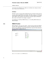
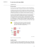
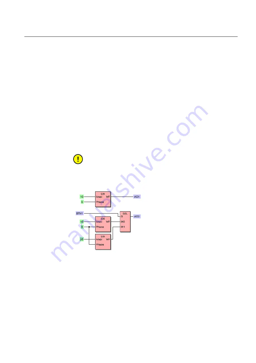
The AO connectors are represented in the IO Editor by the components labelled AO1
through AO10. Each of these corresponds to the physical connector with the same label.
To logically output a signal, the chosen AO component is connected to the WF-output
of a SIN function block, either directly or through a MUX. The connected SIN block is
supplied with an amplitude value and a phase value, upon which a sine wave is generated
and output using the frequency value assigned to the Freq component in the logic.
The value of the amplitude signal determines the value that is perceived by the IED. The
electrical sine wave output has an amplitude maximum of 10 V. This amplitude is
achieved by applying a value of 100 or higher to the amplitude input pin of the SIN
function block connected to the analogue output. The output amplitude can be calculated
by multiplying the value input to the amplitude pin of the SIN block by 100 mV. The
wave generation process responds to changes in the amplitude input value as small as
0.01, corresponding to a 1 mV change in the actual output. The reading displayed by the
IED does not solely depend on the transmitted analogue signal, but also on the settings
of the IED itself.
Depending on the load connected, the output of the analogue
connector may differ from the expected value. This can be
corrected by altering either the IED settings, or the amplitude
input value in the simulation configuration logic.
AO connection.bmp
Figure 4.3-2 AO connectors in IO Editor
Amplifier enable
The UIAMP_ENA object controls the AO amplifiers. When a logical 1 (TRUE) signal
is applied to UIAMP_ENA, the AO amplifiers are powered up and able to output simu-
lation signals. When a logical 0 (FALSE) signal is applied, the AO amplifiers are disabled.
23
Protection System Simulator SIM600
1MRS756102
Installation Manual

