background image

The information icon alerts the reader to relevant facts and
conditions.

The tip icon indicates advice on, for example, how to design
your project or how to use a certain function.

Terminology

1.7.

The following is a list of terms associated with SIM600 that you should be familiar with.
The list contains terms that are unique to ABB or have a usage or definition that is dif-
ferent from standard industry usage. See also 1.8, Abbreviations

Description

Term

Peak value of a sinusoidal quantity.

amplitude

A connector whose output signal is analogue.

analogue output

Informs the IED of on/off states, such as discon-
nector and circuit breaker states, alarm signals
or control functions.

binary output

Device providing connection and disconnection
to a suitable mating component.

connector

See "binary output".

digital output

Connection points to a system. I/O can be digital
(the signal is TRUE or FALSE, for example 0
or 10 V) or analogue (where the signal can vary
from for example 0 to 10 V).

Input/Output

A physical IEC 61850 device that behaves as
its own communication node in the IEC 61850
protocol.

Intelligent Electronic Device

Semiconductor that emits light.

Light Emitting Diode

Measuring relay which, either solely or in com-
bination with other relays, is a constituent of
protection equipment.

protection relay

Abbreviations

1.8.

The following is a list of abbreviations associated with SIM600 that you should be
familiar with. See also 1.7, Terminology.

Description

Abbreviation

Analogue output

AO

7

Protection System Simulator SIM600

1MRS756102

Installation Manual

Summary of Contents for SIM600

Page 1: ...Protection System Simulator SIM600 Installation Manual ...

Page 2: ......

Page 3: ... SIM600 Runtime 12 3 Installing software 13 3 1 Software requirements 13 3 2 Installing SIM600 Editor and SIM600 Runtime 13 4 Connecting SIM600 to IED 17 4 1 Connecting binary I O cables 17 4 2 Connecting analogue output cables 19 4 3 Configuring the connectors 20 5 Mounting Protection System Simulator SIM600 25 5 1 Mounting of Protection System Simulator SIM600 25 6 Uninstalling SIM600 Editor and...

Page 4: ...4 ...

Page 5: ...rpose The software or hardware described in this document is furnished under a license and may be used copied or disclosed only in accordance with the terms of such license Copyright 2007 ABB All rights reserved Trademarks 1 2 ABB is a registered trademark of ABB Group All other brand or product names men tioned in this document may be trademarks or registered trademarks of their respective holder...

Page 6: ...d object in this case The names of push and toggle buttons are boldfaced For example click OK The names of menus and menu items are boldfaced For example the File menu The following convention is used for menu operations MenuName Menu Item For example select File New The Start menu name always refers to the Start menu on the Windows taskbar Use of symbols 1 6 This publication includes warning caut...

Page 7: ...s binary output Device providing connection and disconnection to a suitable mating component connector See binary output digital output Connection points to a system I O can be digital the signal is TRUE or FALSE for example 0 or 10 V or analogue where the signal can vary from for example 0 to 10 V Input Output A physical IEC 61850 device that behaves as its own communication node in the IEC 61850...

Page 8: ...onal Computer PC Power output PO Universal Serial Bus USB Related documents 1 9 MRS number Name of the manual 1MRS756103 Protection System Simulator SIM600 Operator s Manual 1MRS756239 Protection System Simulator SIM600 Configur ation Manual Document history 1 10 History Product revision Document version date Document created 1 0 A 28 9 2007 8 1MRS756102 Protection System Simulator SIM600 Installa...

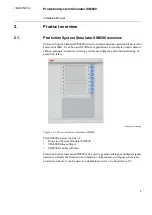
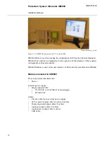
Page 9: ...f protection relays SIM600_front_coi300 jpg Figure 2 1 1 Protection System Simulator SIM600 The SIM600 product consists of Protection System Simulator SIM600 SIM600 Editor software SIM600 Runtime software Protection System Simulator SIM600 can be used to generate analogue and digital signals needed to simulate the function of a substation configuration switchgear system and protection scheme It ca...

Page 10: ...sed as the user interface of Protection System Simulator SIM600 Modules included in SIM600 Protection System Simulator unit Device External power supply Single output AC DC 90 130VAC or 180 260VAC auto ranging 48Vdc 80 W Cables Electric cable for an external power supply 48 Vdc power supply cable to a protection relay Binary input and output cables 2 cables Analogue output cables 5 cables Analogue...

Page 11: ...mulator SIM600 consists of a central unit housed in a metallic case The central unit contains a USB connection to a PC eight pushbuttons and 16 LED indicators For more information on connectors for SIM600 see 4 3 Configuring the connectors SIM600 Editor 2 3 SIM600 Editor is used for configuring Protection System Simulator SIM600 for the required task SIM600 Editor is not mandatory for the operatio...

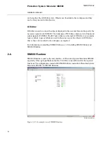
Page 12: ...same way as the objects in GUI Editor that is they can be added to the workspace as required For information on installing SIM600 Editor see 3 2 Installing SIM600 Editor and SIM600 Runtime SIM600 Runtime 2 4 SIM600 Runtime is used as the user interface of Protection System Simulator SIM600 especially if the eight pushbuttons and the 16 LEDs are not sufficient for the required functions The configu...

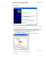
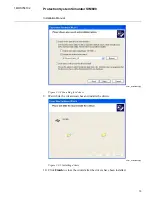
Page 13: ...r or SIM600 Runtime copy the appropriate file to your PC You can run SIM600 Editor and SIM600 Runtime also directly from the CD 3 Connect your PC to Protection System Simulator SIM600 with the USB cable 4 The Found New Hardware Wizard opens Select No not this time to browse for the correct software on your PC 5 Click Next driver_installation1 jpg Figure 3 2 1 Searching for new software 6 Select In...

Page 14: ...rch and browse for one of the three folders on the installation CD Drivers Win2k_XP for Windows 2000 and Windows XP Drivers Win98 for Windows 98 Drivers AMD_64 for 64 bit Windows XP on 64 bit AMD processor browse_for_folder jpg Figure 3 2 3 Browsing for folder containing drivers 8 Click Next 14 1MRS756102 Protection System Simulator SIM600 Installation Manual ...

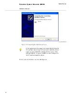
Page 15: ...s 9 Wait while the wizard searches and installs the drivers driver_installation5 jpg Figure 3 2 5 Installing drivers 10 Click Finish to close the wizard after the drivers have been installed 15 Protection System Simulator SIM600 1MRS756102 Installation Manual ...
Page 16: ... the PC and then connect it again If you need to install the drivers again you can uninstall the existing drivers see 6 1 Unin stalling SIM600 or connect SIM600 to a new USB port on the PC and then install the drivers For new versions of drivers see www ftdichip com 16 1MRS756102 Protection System Simulator SIM600 Installation Manual ...

Page 17: ...uit breaker and disconnector trip signals specifically designed for connection to the High Speed Power Outputs HSPO or the power outputs PO of the IED six 2 pin plugs X7 to X12 or digital inputs DI that transfer signals from the IED to SIM600 Connect the cables to the connectors labelled DIGITAL I O 1 and DIGITAL I O 2 on the side panel of SIM600 Protection System Simulator Connect the 3 pin conne...

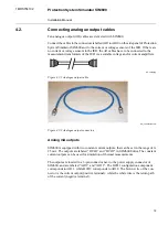
Page 18: ...onstruction Name I O 0 25 mA current source type Usupply 8 75 Vdc DCO1 DCO2 2 analogue current outputs 10V voltage programmable waveform sinusoidal 45 65 Hz AO1 AO10 10 analogue voltage outputs 12 opto isolated 24 60 Vdc inputs and 4 optoisolated 48 Vdc inputs and control for the trip circuit supervision circuit TCS DI1 DI16 TCS1 TCS2 TCS9 TCS10 16 digital inputs Relay output 1 A n o contact REL1 ...

Page 19: ...Figure 4 2 2 Analogue output connectors Analog mA outputs SIM600 is equipped with two constant current outputs that can be set in the range of 0 25 mA The outputs are labeled DCO1 and DCO2 in SIM600 Editor The constant current outputs can be used for simulation of thermal measurements The outputs are located in a 6 pin connector next to the power supply connector of SIM600 and are labeled AO11 and...

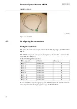
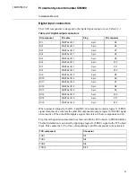
Page 20: ...able 4 3 1 Binary I O connectors I O connector I O cable REL component X1 DIGITAL I O 1 REL 1 2 X2 DIGITAL I O 1 REL 3 4 X3 DIGITAL I O 1 REL 5 6 X4 DIGITAL I O 1 REL 7 8 X1 DIGITAL I O 2 REL 9 10 X2 DIGITAL I O 2 REL 11 12 X3 DIGITAL I O 2 REL 13 14 X4 DIGITAL I O 2 REL 15 16 To activate a REL component apply a logical 1 TRUE signal to the input To deactivate the component return the input signal...

Page 21: ... I O 2 DI13 X10 2 pin DIGITAL I O 2 DI14 X11 2 pin DIGITAL I O 2 DI15 X12 2 pin DIGITAL I O 2 DI16 When connected properly the DI1 2 and DI9 10 components output a logical 1 TRUE signal when inactive whereas the other DI components output a logical 0 FALSE signal when inactive When the IED outputs a signal the states of these components switch Trip Circuit Supervision simulation is achieved with t...

Page 22: ...DIO cable connections jpg Figure 4 3 1 Digital output connections 22 1MRS756102 Protection System Simulator SIM600 Installation Manual ...

Page 23: ... The output amplitude can be calculated by multiplying the value input to the amplitude pin of the SIN block by 100 mV The wave generation process responds to changes in the amplitude input value as small as 0 01 corresponding to a 1 mV change in the actual output The reading displayed by the IED does not solely depend on the transmitted analogue signal but also on the settings of the IED itself D...

Page 24: ...ably If needed the nonlinearity can be manually compensated in the simulation logic Analog mA output bmp Figure 4 3 3 Analog mA output logic Auxiliary power supply The UAUX_ENA object controls the IED auxiliary power supply output labeled POWER OUT located next to the power supply connector of SIM600 When a logical 1 TRUE signal is applied to UAUX_ENA the output powers up and is able to supply pow...

Page 25: ...ions correspond to the dimensions of the SIM600 case They do not include the data transmis sion cables that are connected to the side panels of SIM600 The size of these connectors must be taken into account when mounting To connect the SIM600 simulation cables properly leave an unobstructed space of 80 100 mm next to both side panels Do not use excessive force or bend the cables while mounting SIM...

Page 26: ...Asennuskuva png Figure 5 1 1 Mounting of SIM600 26 1MRS756102 Protection System Simulator SIM600 Installation Manual ...

Page 27: ...w select the Hardware tab 3 Click Device Manager 4 In the Device Manager window open the Universal Serial Bus controllers structure 5 Right click on the PRS USB Device and select Uninstall To uninstall SIM600 Editor and Runtime 1 Disconnect Protection System Simulator SIM600 from your PC 2 Delete the PRS exe and PRSEditor exe files from the hard disk of your PC 27 Protection System Simulator SIM60...

Page 28: ...28 ...

Page 29: ...nnecting binary I O cables 17 D digital input connectors 21 H hardware 11 I installing SIM600 Editor 13 installing SIM600 Runtime 13 M mounting Protection System Simulator SIM600 25 S SIM600 Editor 11 SIM600 overview 9 SIM600 Runtime 12 U uninstalling SIM600 27 29 Protection System Simulator SIM600 1MRS756102 Installation Manual ...

Page 30: ...30 ...

Page 31: ......

Page 32: ...1MRS756102 A ABB Oy Distribution Automation P O Box 699 FI 65101 VAASA FINLAND Tel 358 10 22 11 Fax 358 10 22 1094 www abb com substationautomation ...

Reviews: