Advanced Videographic Recorder
SM2000
Appendix D – Default Settings
124
IM/SM2000
Issue 11
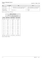
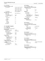
D.1.3 Recording Channels
D.1.4 I/O Modules
Setup
Source indentifiers
Channels 1.1 to 1.6
Analog input A1 to A6
Channels 2.1 to 2.6
Analog input B1 to B6
Trace colors
Channels 1.1 and 2.1
Magenta
Channels 1.2 and 2.2
Red
Channels 1.3 and 2.3
Black
Channels 1.4 and 2.4
Green
Channels 1.5 and 2.5
Blue
Channels 1.6 and 2.6
Brown
Zone (all channels)
Not zoned
Filter type (all channels)
Instantaneous
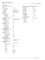
Analog Inputs (A1 to A6 and B1 to B6)
Input type
Type
milliamps
Linearizer Type
Linear
Electrical range low
4.0
Electrical range high
20.0
Engineering range
Low
0.0
High
100.0
Units
%
Short tag
I/P xx
Long tag
Analog input xx
Filter time constant
0 Secs
Fault detect level
10%
Broken sensor direction
Downscale
Digital recording channels
Digital on tag
On
Digital off tag
Off
Short tag
Blank
Long tag
Blank
Process Alarms (all channels)
Alarm type
Off
Recording channel x.x alarm tag
Alarm A tag
x.xA
Alarm B tag
x.xB
Trip
0.0 %
Hysteresis
Hysteresis
0.0 %
Time hysteresis
0 Secs
Enable source
None
Log enable
Off
Alarm group
All None
Totalizers
Count enable
Off
Wrap enable
On
Channel x.x totalizer tag
Total flow x.x
Units
Blank
Stop/Go
Stop/Go recovery
Last
Stop/Go source
None
Count range
Preset count
0
Predetermined count
1000000000
Intermediate count
900000000
Reset source
None
Log update
Log update time
Off
Log update source
None
Count rate/Cut off
Count rate
1.00000
Cut off
0.0
Scales (all channels)
Primary range low
0.0%
Primary range high
100.0%
Secondary range low
0.0%
Secondary range high
100.0%
Scale select source
None
Analog input modules
Mains rejection frequency
50 Hz
Relay modules (all sources)
Source
None
Polarity
Positive
Hybrid modules
Digital outputs
Source
None
Polarity
Positive
Analog outputs
Engineering low
0.0
Engineering high
100.0
Electrical low
4.0
Electrical high
20.0
Analog output source
None


