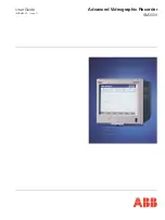
Advanced Videographic Recorder
SM2000
2 OPERATION
IM/SM2000
Issue 11
5
2 OPERATION
2.1 Powering up the Instrument
When power is first applied to the instrument, its processor carries out a number of self-tests and displays the start-up screen.
At the end of the start-up sequence the instrument displays the Operator View that was being displayed when the instrument was
powered down.
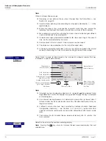
2.2 Displays and Controls – Figs. 2.1 and 2.2
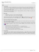
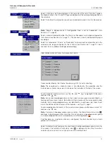
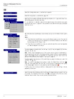
In normal day-to-day use, the instrument is operated via the Operator Keys located along the bottom of the screen.
Fig. 2.1 Displays and Controls
Menu Key
Displays or hides the context-sensitive operator
menu associated with each view.
Group Key
Selects a different
process group.
Up/Down Keys
Highlights menu items and scrolls through
previously recorded data.
View Key
Selects a different process
view or log.
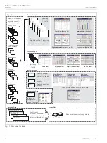
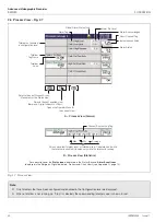
Process Group 1
Process Group 2
Instrument Status & Logs
Chart View
see Section 2.3
Bargraph Views
see Section 2.4
Digital Indicator
View see
Section 2.5
Process View
see Section 2.6
Also cancels the menu without making a change
or returns to the previous menu level.
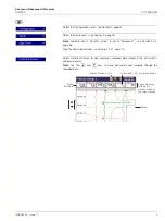
Door Lock
Touch Screen
(Configuration Mode only)
Media Door
Current Date and Time
Programming Socket
(Inside Door)
Infrared Link
Jacking Screw and Fitting for
Tamper-proof Seal
Operator Keys
Digital ON or OFF tag,
according to input status
Channel not enabled
Process Group Name
Short Channel Tag
Current Value
Alarm Status
Engineering Units
Note.
Do not use sharp
objects such as
screwdrivers, pen
nibs etc. to operate
the touch screen.
Clean the touch
screen periodically
using a soft cloth
and mild detergent.
Status Icons – see Appendix G, page 131
Enter Key
Selects the highlighted menu item.
If 'Screen capture' is set to 'Enabled' (see
Section 4.4.1, page 52) and external archive
media is inserted in the instrument, the operator
can save a snapshot of any operator view to the
external media, if pressed when the menu is not
open.

