Advanced Videographic Recorder
SM2000
5 INSTALLATION
106
IM/SM2000
Issue 11
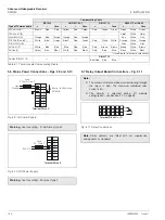
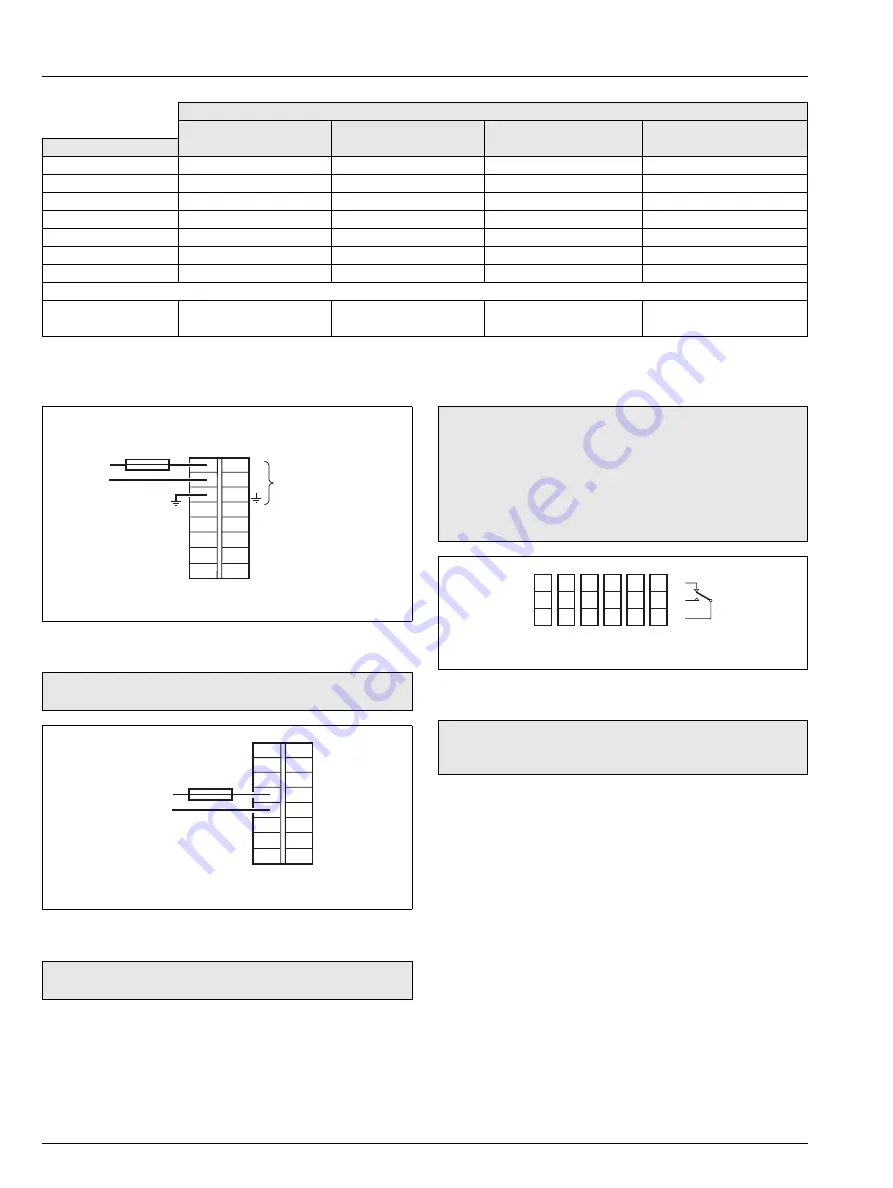
5.6 Mains Power Connections – Figs. 5.9 and 5.10
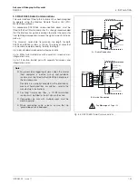
5.7 Relay Output Board Connections – Fig. 5.11
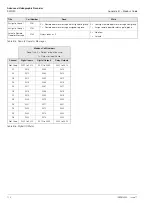
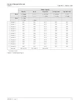
Compensating Cable
BS1843
ANSI MC 96.1
DIN 43714
BS4937 Part No.30
Type of Thermocouple
+
–
Case
+
–
Case
+
–
Case
+
–
Case
Ni-Cr/Ni-Al (K)
Brown
Blue
Red
Yellow
Red
Yellow
Red
Green
Green
Green
White
Green
*
Ni-Cr/Cu-Ni (E)
—
—
—
Violet
White
Violet
*
Nicrisil/Nisil (N)
Orange
Blue
Orange
Orange
Red
Orange
—
Pink
White
Pink
*
Pt/Pt-Rh (R and S)
White
Blue
Green
Black
Red
Green
Red
White
White
Orange
White
Orange *
Pt-Rh/Pt-Rh (B)
—
—
—
Grey
White
Grey
*
Cu/Cu-Ni (T)
White
Blue
Blue
Blue
Red
Blue
Red
Brown
Brown
Brown
White
Brown
*
Fe/Con (J)
Yellow
Blue
Black
White
Red
Black
Red
Blue
Blue
Black
White
Black
*
* Case Blue for intrinsically safe circuits
Fe/Con (DIN 43710)
—
—
DIN 43710
—
Blue/Red
Blue
Blue
Table 5.1 Thermocouple Compensating Cable
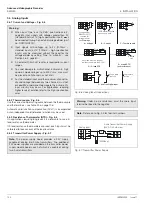
Fig. 5.9 AC Power Supply
Warning.
Use fuse rating – 315mA (max.) type T.
Fig. 5.10 DC Power Supply
Warning.
Use fuse rating – 3A (max.) type T.
Terminal Block E
L
N
85 min. to 265V max.
50/60Hz
1
2
3
4
5
6
7
8
Line
Neutral
Fuse,
315mA, Type T
24V DC
Fuse,
3A, Type T
Terminal Block E
1
2
3
4
5
6
7
8
+
Note.
The maximum total combined current flowing through
the relays is 36A. The maximum individual relay
current is 5A.
The polarity is selected during I/O module
configuration – see Section 4.7.2, page 95.
Fig. 5.11 Relay Connections
Note.
Relay contacts are fitted with arc suppression
components as standard.
17
18
19
14
15
16
11
12
13
7
8
9
4
5
6
1
2
3
Terminal Block C or D
NC
NO
C


