Advanced Videographic Recorder
SM2000
Appendix A – Signal Sources
108
IM/SM2000
Issue 11
Appendix A – Signal Sources
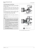
Source Name
Description
Analog Sources
Analog I/P A1
to
Analog I/P B6
Analog input values
(from Analog input module). Available only if an analog input module is fitted in the
relevant position.
Comms AIN 1 to 24
Analog input values
. Received via the Modbus/Modbus TCP serial communications link – see Appendix B,
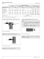
Stats 1.1 max
to
Stats 2.6 max
Maximum Statistics Input Value
. Value since the totalizer on a given channel last wrapped or reset. Available
only on analog channels and if the relevant totalizer is enabled in the Configuration level.
Stats 1.1 min
to
Stats 2.6 min
Minimum Statistics Input Value
. Value since the totalizer on a given channel last wrapped or reset. Available
only on analog channels and only if the relevant totalizer is enabled in the Configuration level.
Stats 1.1 avg
to
Stats 2.6 avg
Average Statistics Input Value
. Value since the totalizer on a given channel last wrapped or reset. Available
only on analog channels and only if the relevant totalizer is enabled in the Configuration level.
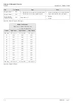
Error States
AIN A1 fail
to
AIN B6 fail
Analog Input Failure
. Active when the signal detected at the analog input is outside the 'Fault Detect Level'
specified in Section 4.6.2.
Comms AIN 1 fail
to
Comms AIN 24 fail
Stats 1.1 fail
to
Stats 2.6 fail
Totalizer Input Value Failure
. Activated when the totalizer fails, cleared when the totalizer wraps or is reset.
Available only for analog channels if the relevant totalizer is enabled in the Configuration level.
Archive media not present
Active when the removable archive media is not present.
Too many files on archive media
Active when there are approximately 300 files on the removable archive media.
Archive 100% full
Active when the removable archive media is 100% full.
Archive 80% full
Active when the removable archive media is 80% full.
Archive media present
Active when the removable archive media is present.
Archive on-line
Active when archiving is in progress.
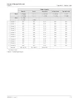
Digital Input States
Digital I/P A1
to
Digital I/P D6
Digital Input States
. From optional hybrid I/O boards fitted at module positions C or D or from analog input
modules fitted at module positions A or B if input 'Type' is set to 'Volt free digital input' – see Section 4.6.2,
page 80. Available only if the module is fitted.
BCD digital I/P D0
to
BCD digital I/P D31
BCD (Binary Coded Decimal) Digital Input States
. Digital states derived from digital inputs D1 to D6.
Available only if optional hybrid I/O board is fitted in module position D.
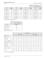
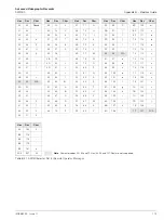
Table A.1 Signal Sources


