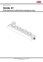
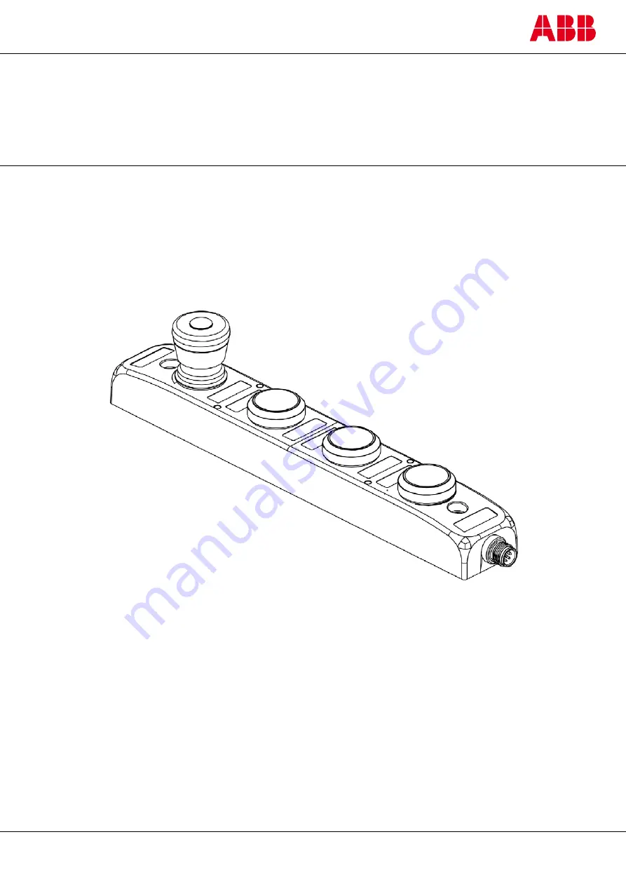
background image

ABB Jokab Safety 

Varlabergsvägen 11, 434 39 Kungsbacka 

www.abb.com/jokabsafety 


Original instructions 

Smile 41 

Push-button box with/without emergency stop 


Summary of Contents for Smile 41 WWWWP

Page 1: ...ABB Jokab Safety Varlabergsvägen 11 434 39 Kungsbacka www abb com jokabsafety Original instructions Smile 41 Push button box with without emergency stop ...

Page 2: ... will provide applicable third party certification documents identifying ratings and limitations of use that apply to the products This information by itself is not sufficient for a complete determination of the suitability of the products in combination with the end product machine system or other application or use The following are some examples of applications for which particular attention mu...

Page 3: ...2 Overview 5 General description 5 3 Connectrions 6 Electrical connections 6 Connection examples 7 4 Installation and maintenance 9 Installation precautions 9 Assembly of colored filters 9 Maintenance 9 5 Operation 10 Emergency stop 10 LED indication 10 6 Model overview 11 Accessories 11 Dimensions 11 7 Technical data 12 8 EC Declaration of conformity 14 ...

Page 4: ...of damage to the equipment An instruction or procedure which if not carried out correctly may damage the equipment NB Notes are used to provide important or explanatory information Safety regulations Warning Carefully read through this entire manual before using the device The devices shall be installed by a trained electrician following the Safety regulations standards and the Machine directive F...

Page 5: ...g a machine for instance to allow start stop and reset when a protective device has been activated Smile 41 is available in different models Smile 41 WWWWP Push button box with four light buttons Smile 41 EWWWP Push button box with emergency stop and three light buttons Warning The emergency stop button must only be used in emergency situations not as a normal stopsignal ...

Page 6: ...ect a possible short circuit between light buttons operative system ver 3 6 or later is needed in Pluto If an older operative system is used unintentional activation of for instance Reset might occur M12 8 pole male connector seen from cable side M12 8 pole female connector seen from cable side M12 8 pole male connector Electrical diagram for Smile 41 EWWWP ...

Page 7: ...2TLC172280M0201 rev C 7 www abb com jokabsafety Connection examples ...

Page 8: ...2TLC172280M0201 rev C 8 www abb com jokabsafety ...

Page 9: ... push buttons colored filters can be pressed over the original push buttons as shown below A kit with five filters in different colors is delivered together with the Smile 41 Maintenance Warning The safety functions and the mechanics shall be tested regularly at least once every year to confirm that all the safety functions are working properly Warning In case of breakdown or damage to the product...

Page 10: ...actuator travel is approximately 4 mm to latch 2 Pull the button until the button is unlatched LED indication The LED in the emergency stop shows a red or a green light depending on if the emergency stop is activated or not The LEDs in the light buttons are controlled by the inputs More details on how this is done with examples are found in the Pluto manual ...

Page 11: ...onnector M12 C03 2TLA020055R1600 Female for field assembly 8 poles with screw terminals Connector M12 C04 2TLA020055R1700 Male for field assembly 8 poles with screw terminals Cable M12 C103 2TLA020056R4000 Female 10m cable 8x0 34mm2 Cable M12 C334 2TLA020056R5100 Male female 3m cable 8x0 34mm2 Cable C8 2TLA020057R1000 Cable per meter 8x0 34 mm2 Kit of colored filters 2TLA030059R2600 Blue green red...

Page 12: ...x 4 mm to latch Approx 4 mm Mechanical life 50 000 operations 1000000 operations B10d 65 000 operations 1300000 operations For the North American market UL Enclosure Type 1 Cable assemblies Must comply with CYJV 7 Cord provided shall be 24 AWG 0 2mm2 minimum Power source The Limited voltage source must comply with a The maximum open circuit voltage potential available to the circuitshall not be mo...

Page 13: ...O 13850 2015 EN 62061 2005 A2 2015 IEC 60664 EN 60204 1 2006 A1 2009 IEC 60664 1 2007 EN 61000 6 2 2005 EN 61000 6 4 2011 EN ISO 13850 2015 EN 60947 5 5 2005 EN 61508 2010 IEC EN 61508 1 7 SIL3 PFDavg 2 95 10 6 PFHD 6 95 10 9 EN 62061 SIL3 EN ISO 13849 1 Performance level PL e category 4 MTTFD High EN 60947 5 1 5 For E stop button safety stop button EN ISO 13850 2008 For E stop button safety stop ...

Page 14: ...2TLC172280M0201 rev C 14 www abb com jokabsafety 8 EC Declaration of conformity ABB JOKAB SAFETY Varlabergsvägen 11 434 39 Kungsbacka www abb com jokabsafety ...

Reviews: