


Main Menu/Settings / IED Settings / Control / Commands / Single Command
or via Parameter Setting Tool (PST).
3.1.2.3
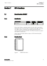
Event function EVENT
M11880-82 v6
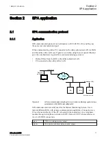
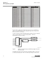
The Event function (EVENT) sends time-tagged events to the station level (for
example, operator workplace) over the station bus. On the station level, events are
presented in an event list. Events can be created from both internal logical signals
and binary input channels. All the internal signals are time tagged in the main
processing module, while the binary input channels are time tagged directly on
each I/O module. Events are produced according to a set of event masks. These
masks are treated commonly for both LON and SPA channels.
Two special signals for event registration purposes are available in the IED:
Terminal Restarted (0E50) and Event buffer overflow (0E51).
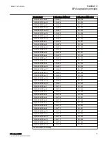
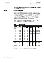
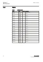
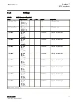
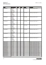
The status and event codes for the EVENT function are found in Table
Table 3:
Status and event codes
Single indication
1)
Double indication
Event block
Status
Set event
Reset
event
Intermedi
ate 00
Closed 10 Open 01 Undefined
11
EVENT:1
Input 1
Input 2
Input 3
Input 4
Input 5
Input 6
Input 7
Input 8
Input 9
Input 10
Input 11
Input 12
Input 13
Input 14
Input 15
Input 16
22O1
22O2
22O3
22O4
22O5
22O6
22O7
22O8
22O9
22O10
22O11
22O12
22O13
22O14
22O15
22O16
22E33
22E35
22E37
22E39
22E41
22E43
22E45
22E47
22E49
22E51
22E53
22E55
22E57
22E59
22E61
22E63
22E32
22E34
22E36
22E38
22E40
22E42
22E44
22E46
22E48
22E50
22E52
22E54
22E56
22E58
22E60
22E62
22E0
22E4
22E8
22E12
22E16
22E20
22E24
22E28
-
-
-
-
-
-
-
-
22E1
22E5
22E9
22E13
22E17
22E21
22E25
22E29
-
-
-
-
-
-
-
-
22E2
22E6
22E10
22E14
22E18
22E22
22E26
22E30
-
-
-
-
-
-
-
-
22E3
22E7
22E11
22E15
22E19
22E23
22E27
22E31
-
-
-
-
-
-
-
-
EVENT:2
EVENT:3
-
-
-
EVENT:20
230..
240..
-
-
-
410..
23E..
24E..
-
-
-
41E..
23E..
24E..
-
-
-
41E..
23E..
24E..
-
-
-
41E..
23E..
23E..
-
-
-
41E..
23E..
24E..
-
-
-
41E..
23E..
24E..
-
-
-
41E..
These values are only applicable if the event mask is masked ≠ OFF.
1MRK 511 418-UEN A
Section 3
SPA operation principle
650 series 2.2 IEC
17
Communication protocol manual


