15
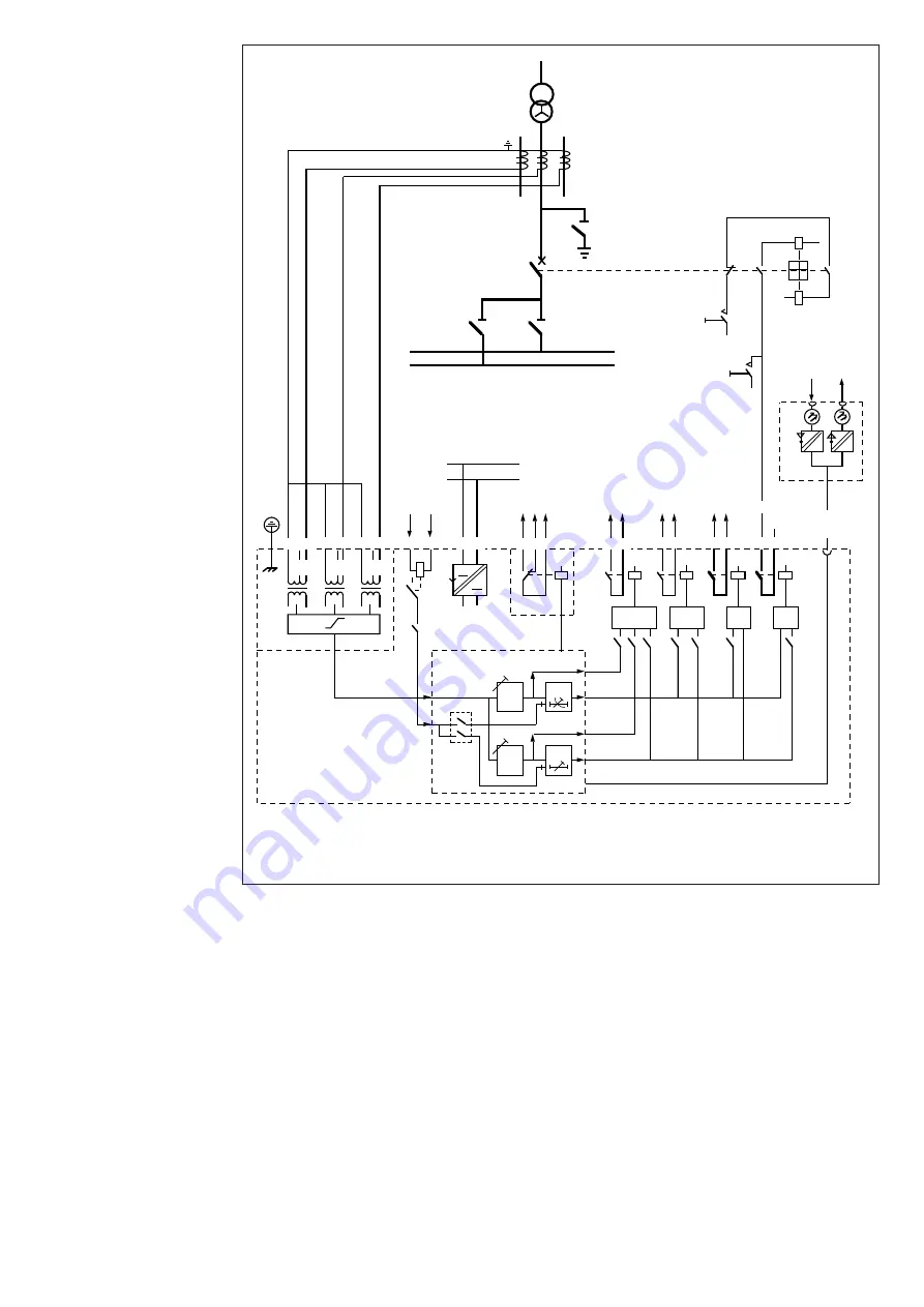
Example 3.
Overcurrent
protection of
the busbar system
in a substation
I
II
0
Ι
0
Ι
-
-
+
+
6
8
7
3
2
4
5A
1A
5
SGR/1
SPAJ 131 C
U2
U3
U3
1
1
1
1
D
C
B
A
+ -
Uaux
E
+
-
(
~
)
(
~
)
5A
1A
5A
1A
5
81
68
66
1 2 3
4
6
7 8 9
10
11
61 62
70 71 72
77 78
80
69
65
SGR
IRF
START1
SIGNAL1
TRIP2
TRIP1
IRF
BS
+
SPA-ZC_
Rx
Tx
TS2
TS1
SGB
SS1
SS2
U1
5
4
I/O
3I>
t >>
t >,k
3I>>
1)
2)
~
SERIAL
PORT
1) Blocking signals from the overcurrent relays of the outgoing feeders
2) Blocking signal to the high-voltage side overcurrent relay of the power transformer
Fig. 7. Overcurrent relay SPAJ 131 C used for protecting the infeeder cubicle and the busbar system.
The switch settings are shown on the next page
In the example in Fig. 7 the low-set stage backs
up the protection of the outgoing feeders, whereas
the high-set stage is used for protecting the
busbar system.
The operation of the busbar protection is based
on blocking signals received from the relay
modules of the outgoing feeders. If a fault occurs
on an outgoing feeder, the overcurrent relay
module of the feeder sends a blocking signal to
the overcurrent module of the infeeder cubicle.
Should, however, the fault be on the busbar
there will be no blocking and the overcurrent
module of the infeeder cubicle provides a trip
signal to the infeeder circuit breaker. In this way
relay times of about 100 ms can be obtained at
a busbar short circuit. If required the blocking
succession can be extended to the overcurrent
module on the HV side of the power trans-
former (see Fig. 4). The trip signal, too, can be
linked from the busbar system to the HV side
circuit breaker of the power transformer. The
wide setting range of the high-set stage makes it
well suited for starting the busbar protection.


