3
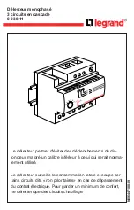
The three-phase voltage relay SPAU 130 C is
intended to be used for overvoltage and under-
voltage protection and supervision in distribu-
tion substations. The relay can also be used for
overvoltage and undervoltage protection of gen-
erators, motors and transformers. Generally the
relay measures the three phase-to-phase voltages
of the system but it can also be programmed for
single-phase measurement.
The overvoltage stage can be given definite time
characteristic or inverse time characteristic. The
undervoltage stage features definite time char-
acteristic alone.
The operation of the undervoltage stage can be
blocked by means of an external control signal.
The relay forms a whole including an over-
voltage stage, an undervoltage stage as well as
flexible trip and alarm functions.
Application
The combined overvoltage and undervoltage
relay SPAU 130 C is a secondary relay that is
connected to the voltage transformers of the
protected object. The relay generally measures
the three phase-to-phase voltages of the system.
On operating the relay trips the circuit breaker
and/or provides alarm, in accordance with the
selected functions and given configuration.
When one of the phase-to-phase voltage or
several exceed the set start value U> of the
overvoltage stage, the overvoltage stage starts
delivering a start signal SS1. When, at definite
time mode of operation, the set operate time t>
or, at inverse time mode of operation, the calcu-
lated operate time t>, has expired, the overvoltage
stage operates delivering a trip signal TS1. In the
same way the undervoltage stage starts deliver-
ing a start signal SS2 when the measured value
goes below the start value U< and when the set
operate time t< has expired, the undervoltage
stage operates, delivering a trip signal TS2.
The overvoltage and undervoltage relay is gen-
erally used as a three-phase relay. But by means
of a selector switch the relay can be configured
as a single phase relay.
The overvoltage stage can be given definite time
characteristic or inverse time characteristic.
When inverse time characteristic is selected two
sets of curves named A and B are available.
The undervoltage stage has definite time charac-
teristic. Tripping of the undervoltage stage can
be blocked by means of a control signal BS
applied to the optically isolated external control
input of the relay.
The overvoltage and undervoltage relay is pro-
vided with two output relays for tripping and
three output relays for signalling purposes. One
of the signalling relays is dedicated for the
selfsupervision system of the relay.
Description
of function
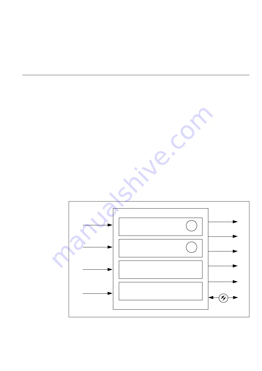
Fig. 1. Protection functions of the combined overvoltage and undervoltage relay SPAU 130 C. The
encircled numbers refer to the ANSI (=American National Standards Institute) number of the
concerned protection function.
THREE-PHASE DEFINITE TIME OR
INVERSE TIME OVERVOLTAGE
STAGE
THREE-PHASE DEFINITE TIME
UNDERVOLTAGE STAGE
EXTERNAL BLOCKING FUNCTION FOR
THE UNDERVOLTAGE STAGE
SERIAL COMMUNICATION
59
27
TRIP 1
TRIP 2
START 1
IRF
SIGNAL 1
SERIAL I/O
U12
BLOCKING
U23
U31


