Controlled Switching — Buyer´s Guide
C-
Edition 2, 2006-09
Introduction - Controlled Switching with Switchsync
TM
Introduction
Application
Suppression of
Switching Transients
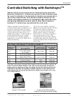
There are several important circuit breaker
applications where random closing or open-
ing instants may lead to severe voltage and
current switching transients. These transients
occur in the main circuits, but may also
induce transients in control and auxiliary cir-
cuits, as well as in adjacent low voltage sys-
tems. The switching transients are associat-
ed with a variety of dielectric and mechanical
stresses on the high-voltage equipment, and
may cause gradual or immediate damage to
the system or the equipment. Induced tran-
sients may lead to a variety of disturbances,
e.g. in substation control and protection
systems, computers and processors, or tele-
communications.
Normal energizing of shunt capacitors, shunt
reactors and power transformers may cause
severe transients - high overvoltages, un-
der-voltages, or high inrush currents. Upon
de-energizing of shunt reactors, reignitions
will occur, resulting in steep voltage surges.
The magnitude of the transients depends on
the point-on-wave where closing or opening
of the circuit breaker contacts occur. In a
situation without controlled switching, sooner
or later the switching instant will occur at the
worst possible phase angle.
Even though a modern circuit breaker will
have very low restrike probability at switch-
ing of capacitive loads or harmonic filters, for
statistical reasons a few occasional restrikes
may occur during the course of a large
number of switching operations. This risk of
occasional restrikes may be eliminated by
means of controlled opening operations.
Conventional countermeasures such as
pre-insertion resistors, damping reactors or
resistors, or arresters are used to limit the
magnitude and effect of the switching tran-
sients, after they have occurred. In addition,
system and equipment insulation may be
upgraded to withstand the stresses. These
methods, however, may be inefficient, unreli-
able or expensive, and do not treat the root
of the problem.
Principle of Controlled Switching
Controlled switching is a method for elimi-
nating harmful transients via time controlled
switching operations. Closing or opening
commands to the circuit breaker are delayed
in such a way that making or contact separa-
tion will occur at the optimum time instant
related to the phase angle.
By means of Switchsync
TM
controllers, both
energizing and de-energizing operations can
be controlled with regard to the point-on-
wave position, and no harmful transients will
be generated.
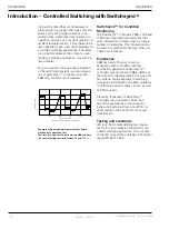
The following example illustrates the general
operating principle of a Switchsync
TM
control-
ler, for energizing of a capacitor bank. In or-
der to avoid switching transients, the making
instant in this case shall be at voltage zero.
For simplicity, only a single phase is consid-
ered.
T
M
T
V
T
F
2EFERENCE
6OLTAGE:ERO
TIME
6OLTAGE
)NPUT
#OMMAND
/UPUT
#OMMAND
0REPROGRAMMED
4ARGET0OINT
T
F
=
Time to detect final reference voltage zero
T
V
=
Waiting time
T
M
=
Expected make time of circuit breaker
REFERENCE
TIME INSTANT
WAITING TIME
+
OPERATING TIME
TARGET TIME
Busbar
Reference
Voltage
Output Command
Circuit
Breaker
Capacitor
Bank
VT
Switchsync
Controller
Input
Command
If controlled opening is applied it is impor-
tant that all protection trip commands, in the
event of fault interruptions, are by-passing
the controller. In secure mode operation the
”controlled way” is typically extended by
about 20 ms at 50 Hz compared to a direct
trip command.

