Controlled Switching — Buyer´s Guide
D-2
Edition 2, 2006-09
Application
Capacitor Banks and Harmonic Filters
Switching of Capacitor Banks and Harmonic Filters
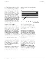
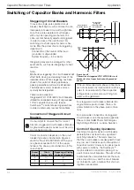
Figure 2.
Voltage transients when energizing one phase of a
72 kV capacitor bank
a. At an unsuitable point-on-wave position, close to
the power frequency voltage peak, a high voltage
transient is generated.
b. With Switchsync
™
controller, energizing occurs
close to voltage zero, and no transient is
generated.
Damping Reactors
Traditionally, damping reactors are often used
for single and back-to-back shunt capacitor
banks. Because these reactors are intended
to limit inrush currents, they are normally su-
perfluous when controlled closing is utilized.
The capacitor bank, circuit breaker, and
system will normally be able to handle the
stresses if an uncontrolled making operation
for some reason should occur.
Figure 3.
Example of making sequences versus the phase-
to-ground busbar voltages for a 50 Hz capacitor
bank. The minor time deviations from voltage zero
across contacts, discussed in Figure 1, have been
disregarded.
Required time staggering for
grounded shunt capacitor bank
Required time staggering for
ungrounded shunt capacitor bank
+ 6.7 ms
+ 3.3 ms
0 ms
0 ms
+ 5 ms
0 ms
One phase of 300 kV, 200 Mvar capacitor bank, Norway
Sometimes, however, damping reactors are
utilized in order to limit high frequency tran-
sients created by interaction of the capacitor
bank with other parts of the network in con-
nection with faults outside that bay. In this
case, the capacitor bank circuit breaker is
not involved, and damping reactors are still
required when controlled switching of the
circuit breaker is used.
Three-phase Conditions
For controlled capacitor bank energizing, the
three circuit breaker poles should close at
different time instants. The time differences
depend on the application.
For capacitor banks with grounded neutral,
the three poles should close in succession
with a time separation of /6 cycle (3.3 ms at
50 Hz or 2.8 ms at 60 Hz).
For capacitor banks with ungrounded neu-
tral, two poles should close simultaneously at
phase - phase voltage zero, and the last one
/4 cycle later (5 ms at 50 Hz or 4.2 ms at 60 Hz)
See Figure 3.


