Controlled Switching — Buyer´s Guide
H-2
Edition 2, 2006-09
Application
Adaptive Functions
Adaptive Functions
For single-pole operated circuit breakers, the
adaptation control can be arranged for each
pole individually.
In the case of three-pole operated circuit
breakers with mechanical staggering, only
one pole will be supervised. The other two
poles are mechanically linked to the con-
trolled one.
Adaptation Control for Opening
Operations
In most cases of controlled opening, the tar-
get consists of a wide range of arcing times
and not a single instant. Therefore, the need
of adaptive control is of less importance
compared to that for controlled closing hav-
ing high demands on precision to make the
current at the correct moment.
If controlled opening is applied, there are two
options depending on the type of operating
mode and type of controller.
The first option is to detect the contact sepa-
ration instant(s) with respect to the selected
reference. This must be arranged by the use
of special precision auxiliary contacts. The al-
ready present auxiliary contacts are normally
not accurate enough. The auxiliary contact
arrangement shall be arranged so that a volt-
age signal will be given to the controller upon
its activation. This method is not reflecting
the result of the interruption.
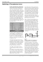
Figure 2.
Example of single-phase reactor energizing.
Current should start at peak voltage.
Real and intended energizing instant marked by
dashed line to the left.
Contact touch instant marked by dotted line to the
right (pre-arcing time = time between energizing
instant and contact touch).
Detection delay, to be programmed, shown by
continuous line.
The second alternative is to use the signal
from the current transformers in the load
branch. The intended interrupting instants
are known by the controller (by its inputs). If
current is still flowing /4 of a cycle or more
after intended interruption, this will be detect-
ed and corrected for in the next controlled
opening operation. Possible with Switch-
sync™ F236.
Adaptive Function of Switchsync
TM
E113, E213 and F236
Using any of these devices for controlled
closing makes it possible to adapt at energiz-
ing instant(s) by detection of current or volt-
age onset instants.
NOTE: For controlled transformer energizing
in adaptive mode using instrument trans-
former signals, voltage start detection (not
current start detection) is required. At opti-
mum targets, the current transformer output
will be far too low and the current harmonics
will introduce an unpredictable detection
delay.
Switchsync™ Controllers E3, E23 and
F236 can also be programmed to operate
in a special mode to detect current change.
This is a useful operating mode when only
one current transformer supervises two
shunt capacitor banks that are switched by
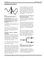
separate circuit breakers; see Figure 3.
For single-pole operated circuit breakers
controlled by either the Switchsync™ E3
or E23 there will be one true adaptation for
one pole while the adaptation control for the
other two poles will be dependent.
Figure 3.
Example of arrangement where adaptation control
of current change detection can be applied for the
controller of the last closing circuit breaker.
CB2
CB1
Voltage Signal
Detection Threshold
Detection Delay
Current Signal
RDDS
time
time


