background image

19

REPLACEMENT PART AND KIT NUMBERS

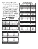
Table 13 – Part Numbers for Replacement Bearings, Single and Double 

Reduction Reducers

Reducer 

Size 

Output Hub Bearing – LH and RH Sides 

Part Number 

TA0107L 

900250/900251 

TA1107H 

901250/901251 

TA2115H 

403003/402003 

TA3203H 

903252/402268 

TA4207H 

403016/402193 

TA5215H 

403140/402050 

TA6307H 

906250/906251 

TA7315H 

403105/402147 

TA8407H 

403105/402147 

TA9415H 

403110/402160 

TA10507H 

910250/910251 

TA12608H 

912250/912251

Reducer 

Size 

Countershaft Bearing – LH Side 

Part Number 

TA0107L 

304833/304740 

TA1107H 

403165/402265 

TA2115H 

304836/411626-05-B 

TA3203H 

403101/402271 

TA4207H 

304809/304710 

TA5215H 

403005/402001 

TA6307H 

403026/906257 

TA7315H 

403159/907260 

TA8407H 

411626-06-BE/411626-05-BM 

TA9415H 

403036/304701 

TA10507H 

403087/402023 

TA12608H 

402233/912253 

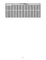
Table 13 – Part Numbers for Replacement Bearings, Single and Double 

Reduction Reducers

Reducer 

Size

Countershaft Bearing – Backstop (RH) Side Part 

Number

TA0107L 

304833/304740 

TA1107H 

403165/402265 

TA2115H 

304836/411626-05-B 

TA3203H 

403101/402271 

TA4207H 

304809/304710 

TA5215H 

403005/402001 

TA6307H 

403026/906257 

TA7315H 

403159/907260 

TA8407H 

411626-06-BE/908253 

TA9415H 

403036/304701 

TA10507H 

403087/402023 

TA12608H 

402233/912253 

Note:

    LH is input side of reducer, and RH is backstop or output side of reducer. Bearing 

part numbers refer to Cup/Cone combinations, respectively, and apply to all ratios 

unless otherwise specified. For actual reducer ratios, refer to Table 12.

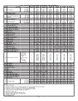
Table 13 – Part Numbers for Replacement Bearings, Single and Double 

Reduction Reducers (Continued.)

Reducer Size

Ratio

Input Shaft Bearing – LH Side

Part Number

TA0107L

5:1 

403166/402284

9:1 
15:1 
25:1 
40:1

TA1107H

5:1 

402169/402294

9:1 
15:1 
25:1 
40:1

TA2115H 

5:1 

403094/304753 

9:1 
15:1 
25:1 
40:1 

403094/304707 

TA3203H 

5:1 

304809/411626-05-K  

9:1 
15:1 
25:1
40:1 

403101/402271 

TA4207H

5:1 

304809/411626-05-K

9:1 
15:1 
25:1 
40:1 

TA5215H

5:1 

403005/402001

9:1 
15:1 
25:1 

403005/304717 

40:1 

Summary of Contents for TA0107L

Page 1: ... reflect our new corporate identity WARNING To ensure the drive is not unexpectedly started turn off and lock out or tag power source before proceeding Failure to observe these precautions could result in bodily injury WARNING All products over 25 kg 55 lbs are noted on the shipping package Proper lifting practices are required for these products WARNING Torque Arm II product exceeding 13 5 kg 30 ...

Page 2: ...chanical Power Transmission Support for proper oil level 3 Mount reducer on driven shaft as follows For Taper Bushed Reducer Mount reducer on driven shaft per instruction in Torque Arm II Bushing Installation section of this manual 4 Install sheave on input shaft as close to reducer as practical Figure 2 5 If not using a Dodge Torque Arm II motor mount install motor and V belt drive so belt will a...

Page 3: ...the reducer must be positioned closer than dimension A place the screws with washers installed in the unthreaded holes in the bushing before positioning reducer making sure to maintain at least 1 8 between the screw heads and the bearing 7 Place the second tapered bushing in position on the shaft and align the bushing keyway with the shaft key Align the unthreaded holes in the bushing with the thr...

Page 4: ...hing screws Tighten the screws lightly If the reducer must be positioned closer than dimension A place the screws with washers installed in the unthreaded holes in the bushing before positioning reducer making sure to maintain at least 1 8 between the screw heads and the bearing 10 Place the long bushing in position on the shaft and align the bushing keyway with the shaft key Use care to locate th...

Page 5: ...ble 8 8 8 4 5 5 5 2 6 2 5 9 15 8 15 0 13 9 13 1 15 3 14 5 TA7315H Single 8 4 8 0 11 8 11 1 13 9 13 2 22 5 21 3 22 1 20 9 25 1 23 7 Double 8 4 8 0 10 8 10 3 13 2 12 5 22 0 20 9 22 4 21 2 23 1 21 8 TA8407H Single N A N A N A N A N A N A N A N A N A N A N A N A Double 7 7 7 3 11 7 11 1 13 7 12 9 25 1 23 8 24 0 22 7 25 8 24 4 TA9415H Single N A N A N A N A N A N A N A N A N A N A N A N A Double 17 0 1...

Page 6: ...ISO grade or AGMA 3 grade for example Mobil SHC627 Above 125 F 51 C consult Mechanical Power Transmission Support Greenville SC for lubrication recommendation 6 Mobil SHC630 Series oil is recommended for high ambient temperatures GUIDELINES FOR TORQUE ARM II REDUCER LONG TERM STORAGE During periods of long storage or when waiting for delivery or installation of other equipment special care should ...

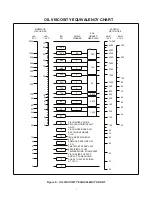
Page 7: ... 3000 4000 5000 6000 8000 10 000 cSt 40 C 100 C cSt ISO VG AGMA GRADES GRADES GEAR OILS SUS 100 F SUS 210 F SAE KINEMATIC VISCOSITIES SAYBOLT VISCOSITIES 200 300 100 90 80 70 60 55 50 45 40 VISCOSITIES CAN BE RELATED HORIZONTALLY ONLY VISCOSITIES BASED ON 96 VI SINGLE GRADE OILS ISO ARE SPECIFIED AT 40 C AGMA ARE SPECIFIED AT 40 C SAE 75W 80W AND 85W SPECIFIED AT LOW TEMPERATURE EQUIVALENT VISCOSI...

Page 8: ...urely installed on the input shaft 4 Recheck fan assembly for proper location and clearance Loosen set screws and repeat steps 2 and 3 above if not properly located Installation for TA6307CF through TA12608CF 1 Referring to Figure 11 install fan guard back plate assembly 1 using the four bolts 4 provided Note that the screen is mounted towards the reducer Tighten to recommended torque in Table 8 C...

Page 9: ...reversing the backstop end for end changes the direction of the arrow The shaft will rotate in the same direction as the arrow on the backstop 5 If the backstop kit has a spacer ring included install it onto the shaft first adjacent to the bearing inner ring 6 Install the backstop inner race and sprag cage assembly onto the shaft DO NOT remove the cage from the inner race or the shipping strap fro...

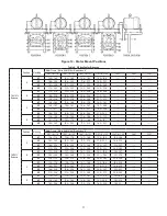
Page 10: ...ts Assemble the remaining jam nuts on studs to secure top motor plate Do not fully tighten these nuts yet The motor mount may be installed in any of the four positions A B C or D and in any of the mounting levels M1 M2 M3 or M4 shown in Figure 12 Note that the motor mount uprights attach to the input side of the reducer when mounted in either the B or D positions Motor Mount Installation WARNING T...

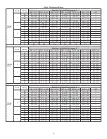
Page 11: ...15 1 18 9 15 9 19 7 M3 16 5 20 3 16 5 20 3 17 5 21 3 18 3 22 1 TA1107L Reducer Position Mounting Motor Frame Motor Shaft Offset Dimensions A 56T A 78 140T A 1 22 180T A 1 37 210T A 1 55 250T A 1 56 280T 320T A M1 13 8 17 9 13 8 17 9 14 7 18 9 15 4 19 6 16 4 20 6 M2 16 2 20 5 16 2 20 5 17 2 21 4 17 9 22 2 18 9 23 2 M3 18 8 23 0 18 8 23 0 19 7 24 0 20 5 24 7 21 5 25 7 M4 21 3 25 6 21 3 25 6 22 3 26 ...

Page 12: ... 6 23 3 27 4 M2 23 3 27 3 24 3 28 3 25 0 29 1 26 0 30 1 26 8 30 8 M3 26 7 30 8 27 7 31 8 28 5 32 5 29 5 33 5 30 2 34 3 C M1 13 6 17 4 14 5 18 4 15 2 19 1 16 2 20 1 16 9 20 8 M2 16 9 20 8 17 8 21 7 18 6 22 5 19 5 23 5 20 2 24 2 M3 20 2 24 2 21 2 25 1 21 9 25 9 22 9 26 9 23 6 27 6 M4 23 6 27 6 24 6 28 5 25 3 29 3 26 3 30 3 27 0 31 0 D M1 10 2 14 2 11 2 15 2 11 9 16 0 12 9 17 0 13 7 17 7 M2 13 6 17 7...

Page 13: ...34 0 31 0 35 0 32 0 36 0 33 0 37 0 M2 32 7 36 7 33 4 37 5 34 4 38 5 35 2 39 2 36 2 40 2 37 2 41 2 38 2 42 2 M3 37 9 41 9 38 6 42 7 39 6 43 7 40 4 44 4 41 4 45 4 42 4 46 4 43 4 47 4 C M1 17 9 21 6 18 6 22 3 19 5 23 3 20 2 24 0 21 1 25 0 22 1 25 9 23 0 26 9 M2 22 8 26 6 23 5 27 3 24 4 28 3 25 2 29 0 26 1 30 0 27 1 31 0 28 0 32 0 M3 27 8 31 7 28 5 32 4 29 5 33 4 30 2 34 1 31 2 35 1 32 1 36 1 33 1 37 ...

Page 14: ... Frame Motor Shaft Offset Dimension A 250T A 1 56 280T A 1 16 320T A 38 360T A 1 01 400T A 75 440T A 1 62 440T A M1 N A N A N A N A N A N A M2 N A N A N A N A N A N A M3 N A N A N A N A N A N A M4 N A N A N A N A N A N A B M1 35 5 39 2 36 2 40 0 37 2 41 0 38 2 42 0 39 2 43 0 40 2 44 0 M2 40 5 44 2 41 2 45 0 42 2 46 0 43 2 47 0 44 2 47 9 45 2 48 9 M3 N A N A N A N A N A N A C M1 N A N A N A N A N A...

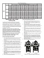
Page 15: ...ware provided assemble the two brackets to the back cover as shown in Figure 16 Note that the brackets are mounted so that the angles of the brackets are mounted to the inside Do not fully tighten these bolts 3 Position back cover over the motor shaft and reducer input shaft The long slot in the back cover fits over the motor shaft 4 Align the back cover assembly to the Torque Arm II motor mount a...

Page 16: ...her type seals and install drive shaft through the adapter housing into the reducer Line up the keyway in the drive shaft with the keyway in the reducer hub bore Slide or gently tap key into reducer through the input shaft side of the output hub 8 Install the retaining ring 411 into the screw conveyor wedge 402 Making sure the drive shaft is fully seated into the reducer slide the wedge onto drive...

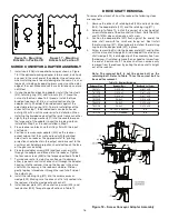
Page 17: ... tap to prevent damage to the threads 4 Remove the outside bushing the reducer and then the inboard bushing Disassembly 1 Drain all oil from the reducer 2 Position the reducer on its side and remove all housing bolts Drive dowel pins from housing Using the three pry slots around the periphery of the flange gently separate the housing halves Open housing evenly to prevent damage to the parts inside...

Page 18: ...03 Loose 002 004 Preload TA4207H 002 004 Loose 0005 003 Loose 002 004 Preload TA5215H 002 004 Loose 0005 003 Loose 003 005 Preload TA6307H 002 004 Loose 0005 003 Loose 006 008 Preload TA7315H 002 004 Loose 0005 003 Loose 006 008 Preload TA8407H 002 004 Loose 0005 003 Loose 004 006 Preload TA9415H 002 004 Loose 0005 003 Loose 004 006 Preload TA10507H 002 004 Loose 0005 003 Loose 006 008 Preload TA1...

Page 19: ...educers Reducer Size Countershaft Bearing Backstop RH Side Part Number TA0107L 304833 304740 TA1107H 403165 402265 TA2115H 304836 411626 05 B TA3203H 403101 402271 TA4207H 304809 304710 TA5215H 403005 402001 TA6307H 403026 906257 TA7315H 403159 907260 TA8407H 411626 06 BE 908253 TA9415H 403036 304701 TA10507H 403087 402023 TA12608H 402233 912253 Note LH is input side of reducer and RH is backstop ...

Page 20: ...tion Reducers Continued Reducer Size Ratio Input Shaft Bearing LH Side Part Number TA6307H 5 1 403026 906260 9 1 15 1 25 1 403026 906257 40 1 TA7315H 5 1 403159 907260 9 1 15 1 25 1 40 1 403159 402054 TA8407H 15 1 908256 908257 25 1 40 1 304804 908258 TA9415H 15 1 411626 06 BE 411626 05 BM 25 1 40 1 304804 908258 TA10507H 15 1 411626 06 BE 411626 05 BM 25 1 40 1 304804 908258 TA12608H 15 1 403036 ...

Page 21: ...908123 908129 908180 25 1 908124 40 1 908125 908130 TA9415H 15 1 909126 909120 909123 909129 909180 25 1 909124 40 1 909125 909130 TA10507H 15 1 910126 910120 910123 910129 910180 25 1 910124 40 1 910125 910130 TA12608H 15 1 912126 912120 912123 912129 912180 25 1 912124 40 1 919125 912130 Seal Kit consists of Input Seal Output Seals and Backstop Cover Gasket Output Hub Assembly consists of Output...

Page 22: ...SSEMBLY 204 205 201 202 203 200 600 413 412 34 36 41 40 38 28 39 35 37 414 415 OPTIONAL BACKSTOP ASSEMBLY 29 45 13 22 30 32 18 31 33 10 11 12 9 TORQUE ARM ASSEMBLY 100 106 108 109 110 101 104 103 105 107 102 111 112 ADJUSTABLE ADAPTER KIT Figure 19 Parts for TA0107L through TA12608H Taper Bushed Double Reduction Reducers ...

Page 23: ...YOR ADAPTER ASSEMBLY ADJUSTABLE ADAPTER KIT 412 413 414 415 600 204 205 201 202 203 200 28 29 45 13 22 30 32 18 31 33 10 11 12 9 OPTIONAL BACKSTOP ASSEMBLY TORQUE ARM ASSEMBLY 100 106 108 109 110 101 104 103 105 107 102 111 112 Figure 20 Parts for TA0107L through TA7315H Taper Bushed Single Reduction Reducers ...

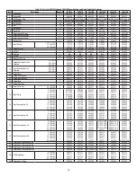
Page 24: ...put Pinion Key 5 1 9 1 15 1 25 1 Ratio 40 1 Ratio 1 1 443634 443634 443634 443634 902277 902277 903277 903298 904277 904277 905277 905277 29 Input Pinion 5 1 Ratio 9 1 Ratio 15 1 Ratio 25 1 Ratio 40 1 Ratio 1 1 1 1 1 900222A 900221A 900220A 900219A 900218A 901222A 901221A 901220A 901219A 901218A 902222 902221 902220 902219 902218 903222 903221 903220 903219 903218 904222 904221 904220 904219 90421...

Page 25: ...11 419011 419013 Adapter Hardware Kit 1 900070 901070 902070 903070 904070 905070 400 Screw Conveyor Adapter 1 900401 901401 902401 903401 904401 905401 401 Screw Conveyor Keeper Plate 1 900402 901402 902402 903402 904402 905402 402 Screw Conveyor Wedge 1 900403 901403 902403 903403 904403 905403 403 Screw Conveyor Drive Shaft 1 1 2 Shaft 1 1 2 Shaft Stainless Steel 2 Shaft 2 Shaft Stainless Steel...

Page 26: ...105 403110 910250 912250 25 Output Bearing Cone 2 906251 402147 402147 402160 910251 912251 26 Output Hub 1 906230 907230 908230 909230 910230 912230 27 Output Gear Key 1 906275 907275 908275 909275 910275 912275 28 Input Pinion Key 5 1 9 1 15 1 25 1 Ratio 40 1 Ratio 1 1 1 906277 906277 906277 907277 907277 907277 N A 908277 908277 N A 909277 909277 N A 909277 909277 N A 909277 909277 29 Input Pin...

Page 27: ... 200 Bushing Back Up Plate 2 906301 272037 908301 909301 910301 912301 203 Retaining Ring 2 906304 421098 908304 909304 910304 912304 204 Bushing Cap Screw 6 411456 411457 411457 032018016EJ 032018016EJ 032018016EJ 205 Bushing Lockwasher 6 419013 419013 419013 032018016EJ 032018016EJ 032018016EJ 400 Screw Conveyor Adapter 1 906401 907401 N A N A N A N A 401 Screw Conveyor Keeper Plate 1 906402 907...

Page 28: ...03 15 619 25 067 33 333 TA3203H 4 913 9 234 15 067 24 954 32 451 TA4207H 5 000 9 231 15 000 25 125 39 107 TA5215H 5 105 9 183 14 923 24 996 38 907 TA6307H 4 944 9 215 15 451 24 868 38 319 TA7315H 5 188 9 716 14 914 24 837 39 656 TA8407H N A N A 15 120 24 965 39 667 TA9415H N A N A 15 103 25 435 39 406 TA10507H N A N A 15 092 25 184 39 676 TA12608H N A N A 14 788 25 025 38 188 ...

Page 29: ...tationery parts The installation should be in accordance with the conditions in the following sections The reducer is designed to operate with a surface temperature at or below 200 F Failure to operate the reducer properly can cause this maximum surface temperature to be exceeded If applied in a Division 1 or Zone 1 environment this excessive temperature may cause ignition of hazardous materials T...

Page 30: ...he following EC Directive s when installed in accordance with the installation instructions contained in the product documentation 2014 34 EU ATEX and that the standards and or technical specifications referenced below have been applied EN 13463 1 2009 Non Electrical Equipment For Potentially Explosive Atmospheres Method And Requirements EN13463 5 2011 Non Electrical Equipment Intended For Use In ...

Page 31: ...31 ...
Page 32: ...rt Smith AR 72901 Ph 1 479 646 4711 Mechanical Power Transmission Support Ph 1 864 297 4800 new abb com mechanical power transmission baldor com All Rights Reserved Printed in USA 09 18 Litho 25 000 ABB Motors and Mechanical Inc MN1601 Replaces 499314 1601 0918 ...

Reviews: