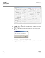
GUID-F30E8D82-95A5-4460-AAEE-BBCD9FAD3FEB V1 EN
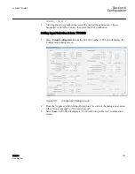
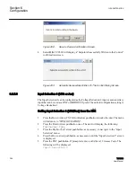
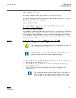
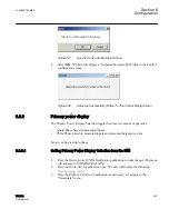
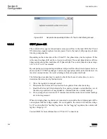
Figure 298:
Setpoints Successfully Written To The Control Dialog Screen
6.2.9.4
CT/VT phase shift
The control will recognize forward and reverse power flow to the load. With the CT and
VT (reference) signals in-phase for unity power flow to the load, it will properly calculate
line drop compensation.
Depending on the connection of the CT and VT, the phasors may not be in
‑
phase. If this
is the case, the phase shift can be corrected in software. The usual characteristics of three
phase systems only allow multiples of 30° phase shifts. The control, therefore, has a range
of 0° to 330° in 30° increments.
By comparing system operating conditions with power flow direction and power factor as
shown on the TCC300 Tapchanger Control, improper phase shift can be determined. An
incorrect connection may be resolved using well-known phasor methods.
The following procedure may be useful to check the choice of correction or even to
determine the correction by trial and error:
1. Place the regulator in manual control.
2. Determine the Watts and VArs load on the regulator from other metering.
3. Read the Watts and VArs indicated by the control, and make certain that they are of
the same sign and ratio of magnitudes as obtained from the external readings.
4. If not, change the correction in 30° increments until the control and external readings
are in best agreement.
When two single-phase regulators are connected in open delta, the current signals will be
out-of-phase with the voltage signals. For one regulator, the current will lead the voltage
by 30° and is called the "leading" regulator. For the "lagging" regulator, the current will
lag the voltage by 30°.
Contact ABB for more information on VT and CT connections.
Section 6
1VAC388793-MB A
Configuration
368
TCC300
User Manual
Summary of Contents for TCC300
Page 1: ...Digital Tapchanger Control TCC300 User Manual ...
Page 2: ......
Page 3: ...Document ID 1VAC388793 MB Issued 2016 08 10 Revision A Copyright 2016 ABB All rights reserved ...
Page 26: ...20 ...
Page 34: ...28 ...
Page 91: ...1VAC388793 MB A Section 3 Operation TCC300 85 User Manual ...
Page 126: ...120 ...
Page 176: ...Section 4 1VAC388793 MB A TCC600 170 TCC300 User Manual ...
Page 260: ...254 ...
Page 328: ...322 ...
Page 494: ...488 ...
Page 556: ...550 ...
Page 580: ...574 ...
Page 600: ...594 ...
Page 700: ...694 ...
Page 710: ...704 ...
Page 712: ...706 ...
Page 713: ...707 ...
Page 714: ......
Page 715: ......


