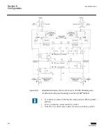
is a schematic of the current circuit only; redrawn from the Paralleling Scheme
figures to allow easier tracing of the load current (IL) and circulating current (Ip) paths.
current, is fed to the M
‑
0115A unit. Because of the secondary parallel connection,
however, this is actually the vector sum of the desired load current and any undesired
circulating current. The M
‑
0115A separates these currents, and sends them to the proper
load (LDC) and circulating current inputs of the associated control.
Two current loops are formed. One involves the K3 auxiliary transformers in each of the
M
‑
0115A units. This loop forms a measure of the transformer bank circulating current,
subtracted from the LDC control input and forced to flow into the control circulating
current input.
The second loop involves the K1 and K2 auxiliary transformers. They force the load
current to divide properly between the various controls so that each senses its proper
portion of the total bank load. Thus, the LDC setting for each control may properly be the
same, regardless of whether or not the associated transformer is being used in parallel.
The first current path shown (Circulating Current) has a current analogous in angle and
magnitude to the reactive current circulating through the paralleled transformers. It also
includes the M
‑
0127A Overcurrent Relay, which is used to detect excessive circulating
current and block the tapchanger movement, if this occurs. Also, a lamp will alert the
operator when excessive circulating current is detected.
The second path shown (Balance Current), connecting the K1 auxiliary CT of the
M
‑
0115A modules together, has a balance current which forces the two load currents of
transformers #1 and #2 to be identical. This means that any difference in currents must
flow in the circulating current path.
The third and fourth path shown (Half Current and LDC Current), connecting the K2
auxiliary CT of the M
‑
0115A modules together, ensures proper operation of the Load
Drop Compensator circuit if one of the transformers is taken out of service by opening its
breaker. For instance, if transformer #2 is taken out of service by opening breaker 52-2,
then half of transformer #1's load current is forced to flow through the half current loop.
In this way, transformer #1's voltage regulating control sees the same load current as it did
before, and the proper amount of line drop compensation in the transformer #1 control is
maintained. This circuit configuration and grounding points must be maintained, if
transformers are to be successfully paralleled.
A more detailed description of the theory of operation is available from ABB upon
request. Application Note #11, "Introduction to Paralleling of LTC Transformers by the
Circulating Current Method" and Application Note #13, "Advanced Paralleling of LTC
Transformers by the Circulating Current Method" provide a thorough analysis of parallel
LTC transformers operating by the circulating current method.
1VAC388793-MB A
Section 6
Configuration
TCC300
403
User Manual
Summary of Contents for TCC300
Page 1: ...Digital Tapchanger Control TCC300 User Manual ...
Page 2: ......
Page 3: ...Document ID 1VAC388793 MB Issued 2016 08 10 Revision A Copyright 2016 ABB All rights reserved ...
Page 26: ...20 ...
Page 34: ...28 ...
Page 91: ...1VAC388793 MB A Section 3 Operation TCC300 85 User Manual ...
Page 126: ...120 ...
Page 176: ...Section 4 1VAC388793 MB A TCC600 170 TCC300 User Manual ...
Page 260: ...254 ...
Page 328: ...322 ...
Page 494: ...488 ...
Page 556: ...550 ...
Page 580: ...574 ...
Page 600: ...594 ...
Page 700: ...694 ...
Page 710: ...704 ...
Page 712: ...706 ...
Page 713: ...707 ...
Page 714: ......
Page 715: ......


