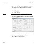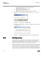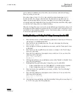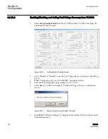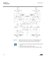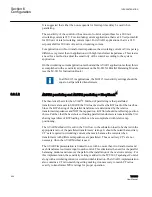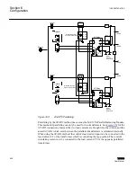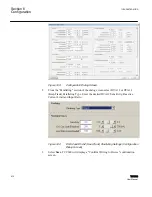
It is suggested that either the non
‑
sequential or Intertap time delay be used when
paralleling.
The sensitivity of the control or the amount of control setpoint bias for a 200 mA
circulating current is 24 V. For circulating current applications, that is a 24 V setpoint shift
for 200 mA of total circulating current input. For ΔVAR1 applications, that is a 24 V
setpoint shift for 200 mA of reactive circulating current.
For applications with low transformer impedances, the circulating current or VArs per tap
difference is greater than in applications with high transformer impedances. This creates
a need for a method to adjust the sensitivity of the control according to the system
application.
On the circulating current application method and the ΔVAR1 application method, this is
accomplished with a sensitivity adjustment on the M
‑
0115A Parallel Balancing Module
(see the M
‑
0115A Instruction Book.)
In all M
‑
0115A applications, the M
‑
0115A sensitivity settings should be
equal on all paralleled transformers.
6.3.1.2
ΔVAR2 paralleling and ΔVAR2 paral KeepTrack
™
The theoretical basis for the ΔVAR
®
2 Method of paralleling is that paralleled
transformers are meant to SHARE the VAr load (as well as the KW load) of the load bus.
Since the KW sharing of the parallel transformers is determined by the relative
transformer impedances and NOT the tap position, KW flow should not effect tap position
choice. Further, that the best choice of loading parallel transformers is to maintain the VAr
sharing regardless of KW loading which can be accomplished with relative tap
positioning.
The ΔVAR Method will result in the VAr flow to the substation load to be shared in the
appropriate ratio of the paralleled transformers’ ratings. It should be noted that auxiliary
CT’s are required in circulating current schemes to balance the currents when
transformers with different impedances are paralleled. Those auxiliary CT’s are not
necessary when the ΔVAR Method is used.
The ΔVAR2 implementation is limited to use with no more than two transformers and
each transformer current is input to each control. This eliminates the need for the parallel
balancing module and removes the path for the installation of the overcurrent relay. For
this implementation, the sensitivity setting is added to the TCC300 Tapchanger Control
along with a circulating current overcurrent inhibit function. The ΔVAR2 implementation
also contains a CT ratio-matching setting making it unnecessary to match CT ratios
exactly to transformer MVA ratings for proper operation.
Section 6
1VAC388793-MB A
Configuration
404
TCC300
User Manual
Summary of Contents for TCC300
Page 1: ...Digital Tapchanger Control TCC300 User Manual ...
Page 2: ......
Page 3: ...Document ID 1VAC388793 MB Issued 2016 08 10 Revision A Copyright 2016 ABB All rights reserved ...
Page 26: ...20 ...
Page 34: ...28 ...
Page 91: ...1VAC388793 MB A Section 3 Operation TCC300 85 User Manual ...
Page 126: ...120 ...
Page 176: ...Section 4 1VAC388793 MB A TCC600 170 TCC300 User Manual ...
Page 260: ...254 ...
Page 328: ...322 ...
Page 494: ...488 ...
Page 556: ...550 ...
Page 580: ...574 ...
Page 600: ...594 ...
Page 700: ...694 ...
Page 710: ...704 ...
Page 712: ...706 ...
Page 713: ...707 ...
Page 714: ......
Page 715: ......


