The measured voltage the TCC300 controls on each of the transformers will be biased in
such a way as to attempt to minimize the circulating current between the two. In the case of
ΔVAR, the tap positions will minimize the difference in VArs from each transformer.
For ΔVAR2 applications, there is a 24 V setpoint shift for 200 mA of calculated reactive
current difference between transformers. (ΔVAR2 is only applicable for two parallel
transformer applications.)
For applications with low transformer impedances, the circulating current or VArs per tap
difference is greater than in applications with high transformer impedances. This creates
a need for a method to adjust the sensitivity of the control according to the system
application.
On the ΔVAR
®
2 application method, which uses no M
‑
0115A module, a control setting
is provided to accomplishment the sensitivity adjustment.
In all ΔVAR2 applications, the sensitivity settings should be equal on all
paralleled transformer controls.
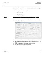
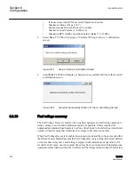
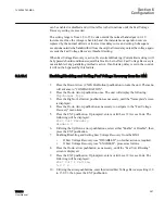
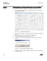
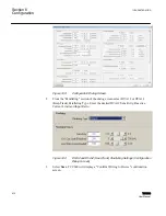
Exclusively for the ΔVAR2 method, there are three functions activated and set in the
Configuration menu for proper operation: ΔVAR2 Sensitivity, ΔVAR2 Reac Limit, and
ΔVAR2 I Ratio. When the ΔVAR option has not been purchased, these input screens will
be disabled.
The ΔVAR2 Sensitivity ranges from –4.0 to +4.0, as did the M
‑
0115A adjustment. At a
ΔVAR2 Sensitivity setting of 0.0, 100% of calculated reactive current difference will be
used to bias the setpoint. At a setting of –4.0, only 50% of the calculated reactive current
difference will be used to bias the setpoint, making the control less sensitive to the
circulating current. At a setpoint of +4.0, the bias will be adjusted by a value of 200% of
the calculated reactive current difference, making the control more sensitive to the system
current.
The ΔVAR2 Circ Limit I setpoint establishes a limit on the calculated reactive current
difference between transformers. The settings range from 5 mA to 200 mA in 1 mA
increments. If the calculated reactive current difference reaches this setpoint, the
operation of the control will be blocked and the alarm output function will be activated, if
enabled. The purpose of this limit is to stop any runaway condition. This feature is
required to replace the M
‑
0127A overcurrent relay used in the circulating current and
ΔVAR1 applications.
Care must be taken in setting the ΔVAR2 Circ Limit I, to ensure it is high
enough to allow a two or three tap difference from optimum in
transformers before operating. Some knowledge of system impedances
are useful in determining this setting, but the current difference may also
1VAC388793-MB A
Section 6
Configuration
TCC300
407
User Manual
Summary of Contents for TCC300
Page 1: ...Digital Tapchanger Control TCC300 User Manual ...
Page 2: ......
Page 3: ...Document ID 1VAC388793 MB Issued 2016 08 10 Revision A Copyright 2016 ABB All rights reserved ...
Page 26: ...20 ...
Page 34: ...28 ...
Page 91: ...1VAC388793 MB A Section 3 Operation TCC300 85 User Manual ...
Page 126: ...120 ...
Page 176: ...Section 4 1VAC388793 MB A TCC600 170 TCC300 User Manual ...
Page 260: ...254 ...
Page 328: ...322 ...
Page 494: ...488 ...
Page 556: ...550 ...
Page 580: ...574 ...
Page 600: ...594 ...
Page 700: ...694 ...
Page 710: ...704 ...
Page 712: ...706 ...
Page 713: ...707 ...
Page 714: ......
Page 715: ......


