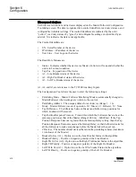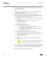
Discovered devices
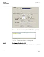
Each discovered control and its data is displayed on the Master/Follower Configuration
Tool dialog screen. The data is organized into control identifiers, read only statuses, and
configurable (writable) settings. The control identifiers are indicated by the color
"yellow", read only statuses by "green", and configurable settings are identified by an
asterisk. NA indicates the data is not applicable.
The Control Identifiers are:
•
SN – Serial Number of the device
•
IP Address – IP address of the device
•
User Line – User Logo on the device
The Read Only Statuses are:
•
Status – Indicates whether the device is a Master, Follower or None and whether the
unit is in Lockout condition.
•
Tap Pos – Tap position of the device
•
A1 – Line Breaker status of the device
•
A2 – Right Tie Breaker status of the device
•
A3 – Left Tie Breaker status of the device
A1, A2, and A3 are references to the TCC300 Auxiliary Inputs.
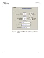
The Configuration Tool allows the user to enter the following settings:
•
Paralleling Mode – Master/Follower Paralleling Mode is automatically changed to
Master/Follower when settings are written to the control.
•
Paralleling Address – The unique address for each device (Range 1 – 16)
•
Mode – Master/Follower mode of operation. M = Master, F= Follower, N = None
•
Tap Difference – The difference between Master and Follower tap positions for
which Lockout will be issued.
•
Tap Position Response Timeout – Time within which the Followers have to be at the
same tap position as that of the Master (Range 1000 ms – 60000 ms). If the Tap
Position Response Timeout is greater than the Intertap Delay setting, then the Tap
Position Response Timeout is used as the Intertap Delay, so that the Master waits for
all the Followers to make a tapchange before the Master takes the next tap.
•
# Devices – The number of total devices that are in the paralleling scheme (maximum
16 inclusive of the Master)
•
Breaker In Use (A1) – Option to use the Line Breaker Status in the algorithm.
•
Breaker Polarity – Positive or negative polarity of the Line Breaker.
•
Right TB In Use (A2) – Option to use the Right Tie Breaker Status in the algorithm.
•
Right TB Polarity – Positive or negative polarity of the Right Tie Breaker.
•
Left TB In Use (A3) – Option to use the Left Tie breaker Status in the algorithm.
•
Left TB Polarity – Positive or negative polarity of the Left Tie Breaker.
Section 6
1VAC388793-MB A
Configuration
416
TCC300
User Manual
Summary of Contents for TCC300
Page 1: ...Digital Tapchanger Control TCC300 User Manual ...
Page 2: ......
Page 3: ...Document ID 1VAC388793 MB Issued 2016 08 10 Revision A Copyright 2016 ABB All rights reserved ...
Page 26: ...20 ...
Page 34: ...28 ...
Page 91: ...1VAC388793 MB A Section 3 Operation TCC300 85 User Manual ...
Page 126: ...120 ...
Page 176: ...Section 4 1VAC388793 MB A TCC600 170 TCC300 User Manual ...
Page 260: ...254 ...
Page 328: ...322 ...
Page 494: ...488 ...
Page 556: ...550 ...
Page 580: ...574 ...
Page 600: ...594 ...
Page 700: ...694 ...
Page 710: ...704 ...
Page 712: ...706 ...
Page 713: ...707 ...
Page 714: ......
Page 715: ......


