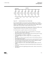
LB1 through LB8 are Line Breakers and TB1-2 through TB8-1 are the Tie Breakers which
take the transformer out of paralleling. Transformer 8 is connected to Transformer 1
through the Tie Breaker TB8-1 which makes the single bus a special case of a ring bus.
To isolate a single transformer or create two sub-networks, at least two Tie Breakers must
be open. For example, consider
. When it is time for the control in Position 8
on the ring bus to publish its GOOSE message, the control will determine whether Tie
Breakers TB8
‑
1 and TB7
‑
8 are both open. This would create two sub-networks.
Transformers 7 & 8 would be one paralleled network, and transformers 1 through 6 would
be a separate paralleled network. Each network would operate individually as separate
parallel groups.
The Ring Bus application is similar to a Single Bus application except that the last
designated control in the ring must evaluate the TB8-1 Tie Breaker and adjust the Delta
VAr Peer to Peer Paralleling system accordingly.
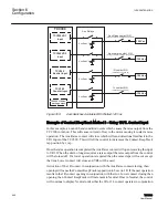
Double bus
represents a Double Bus with eight transformers.
TCC300
T1
Position 1
i1
TCC300
T2
Position 2
i2
TCC300
T3
Position 3
i3
TCC300
T4
Position 4
i4
TCC300
T5
Position 5
i5
TCC300
T6
Position 6
i6
TCC300
T7
Position 7
i7
TCC300
T8
Position 8
i8
LB1
LB2
LB3
LB4
LB5
LB6
LB7
LB8
DB1-A
DB2-A
DB3-A
DB4-A
DB5-A
DB6-A
DB7-A
DB8-A
DB1-B
DB2-B
DB3-B
DB4-B
DB5-B
DB6-B
DB7-B
DB8-B
Double Bus
High Side Bus
Low Side Bus A
Low Side Bus B
GUID-83AC47C0-A8FA-43FA-BFD0-1E4D259BF912 V1 EN
Figure 350:
Double Bus Breaker/Control Network Map
LB1 through LB8 are the Line Breakers. DB1-A through DB8-A and DB1-B through
DB8-B are Double Bus Breakers, which connect the transformer to either the Low Side
Bus A or Low Side Bus B, or both.
There are two Low Side buses which the transformer can drive. The user must enter the
position of the control in the network. The downstream control should be given position
1 and consecutively increment this number as the user moves towards the right most
control. The Initiator address is incremented based on the Line breaker.
In a Double Bus application, paralleling groups are formed in the following ways:
1VAC388793-MB A
Section 6
Configuration
TCC300
433
User Manual
Summary of Contents for TCC300
Page 1: ...Digital Tapchanger Control TCC300 User Manual ...
Page 2: ......
Page 3: ...Document ID 1VAC388793 MB Issued 2016 08 10 Revision A Copyright 2016 ABB All rights reserved ...
Page 26: ...20 ...
Page 34: ...28 ...
Page 91: ...1VAC388793 MB A Section 3 Operation TCC300 85 User Manual ...
Page 126: ...120 ...
Page 176: ...Section 4 1VAC388793 MB A TCC600 170 TCC300 User Manual ...
Page 260: ...254 ...
Page 328: ...322 ...
Page 494: ...488 ...
Page 556: ...550 ...
Page 580: ...574 ...
Page 600: ...594 ...
Page 700: ...694 ...
Page 710: ...704 ...
Page 712: ...706 ...
Page 713: ...707 ...
Page 714: ......
Page 715: ......


