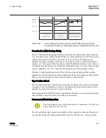
Load grows
Raise operation blocked at
t = T
1
Voltage increases further
due to system switching
Lower command issued at
t = T
2
t
t
t
130
128
120
114
V
LOCAL
Low Load
No action on part of
voltage limit control
T
1
T
1
T
2
Overvoltage
Runback
Block Raise
Bandcenter
Block Lower
Local voltage Raised Due to LDC
GUID-E5B263AB-E207-4E81-B7FE-0950C954B896 V1 EN
Figure 394:
Local Voltage as Function of Load Current When Using Line Drop
Compensation/ Action of Overvoltage and Overvoltage Runback Control
Coordination with Backup Relay
The TCC300 Digital Tapchanger Control provides the first customer protection functions.
Use of a backup relay, such as the M
‑
0329B, is recommended since the TCC300 (or any
independent control) cannot be expected to be its own backup. The backup relay
bandcenter setting is usually set the same as the primary control, with the bandwidth
setting 1 or 2 volts greater than the primary control bandwidth, the block raise setting 1
volt greater than the primary control, and the deadband setting 1 or 2 volts. These settings
create a runback level 1 or 2 volts above the runback level of the primary control.
If primary control operation is desired first, the block raise setting and the resulting
runback level of the backup relay must be higher than those of the primary control and the
block lower setpoint must be lower than the primary control setting.
Tap Position Block
The Tap Position Block is disabled by setting the Tap Information screen to the Disable
condition. If the Tap Information screen is not disabled, the Tap Position block can be
disabled by setting the Tap Limits screen to Disable.
When using the M
‑
2025B(D) Current Loop Interface Module, a one-second intertap time
delay should be used, due to the time setting of the module.
Overcurrent Block Operation
The current input to the control is rated at 0.2 A continuous, 0.4 A for two
hours, and 4.0 A for 1 second.
The Current Block Limit setpoint is available to block operation whenever the current
exceeds the setting. The setting is adjustable from 50 to 640 mA in 1 mA increments.
1VAC388793-MB A
Section 7
Setpoints
TCC300
495
User Manual
Summary of Contents for TCC300
Page 1: ...Digital Tapchanger Control TCC300 User Manual ...
Page 2: ......
Page 3: ...Document ID 1VAC388793 MB Issued 2016 08 10 Revision A Copyright 2016 ABB All rights reserved ...
Page 26: ...20 ...
Page 34: ...28 ...
Page 91: ...1VAC388793 MB A Section 3 Operation TCC300 85 User Manual ...
Page 126: ...120 ...
Page 176: ...Section 4 1VAC388793 MB A TCC600 170 TCC300 User Manual ...
Page 260: ...254 ...
Page 328: ...322 ...
Page 494: ...488 ...
Page 556: ...550 ...
Page 580: ...574 ...
Page 600: ...594 ...
Page 700: ...694 ...
Page 710: ...704 ...
Page 712: ...706 ...
Page 713: ...707 ...
Page 714: ......
Page 715: ......


