•
Desired Bandcenter = 120 volts
•
Desired Bandwidth = 2 volts
•
The device being controlled is 50% loaded
Setting
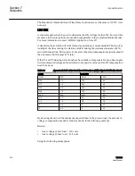
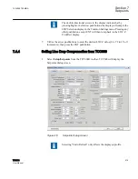
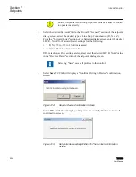
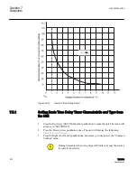
Start with R=0 and X=0 and increase both values using the ratio shown in the table for the
feeder conductor. Keeping the R/X ratio, increase Rset and Xset until the difference
between the compensated voltage and the local voltage is 2.0 volts.
This example would let the voltage vary from 119 V at no load to 125 V at maximum load
taking into account the bandwidth.
With this simplified method of LDC setting, the first customer’s voltage will be limited by
the upper voltage limit at the highest daily load, depending on the accuracy of the daily
load projection. At the same time, the furthest customer will receive the highest voltage
possible under the line and loading conditions. The first customer protection can be set on
the control.
Since the daily load projections will likely have a seasonal variation, the best balance of
first customer to furthest customer voltage may require seasonal adjustment of the LDC
settings. Note that the settings of R and X compensation are proportional to the peak load
projection and that new settings can be scaled from the first setting obtained by the
experimental process just described.
LDC‑Z
The second available compensation method is called Z-compensation (LDC-Z). LDC-Z
must be selected in the control setpoint portion of the menu or software and the
VOLTAGE RAISE (V
R
) setpoint must be set in order for this feature to be implemented.
The LDC-Z application is especially useful on systems where several lines exist with
different load centers where the proper compensation is not related to any single R & X
values as set in R & X compensation.
Basically, LDC-Z compensation consists of designating a target bus voltage increase (line
drop compensation) that correlates to the magnitude of the control current rather than to
the calculation of input R & X line drop at control current magnitude and angle values.
The setting, (VR), is the calculated load voltage drop (at maximum load) in the circuit or
line that has the ratio of the highest voltage drop at maximum load condition compared to
the rated CT output (200 mA).
V
R
= 0 to 72 volts in increments of 1 volt.
Example:
1VAC388793-MB A
Section 7
Setpoints
TCC300
515
User Manual
Summary of Contents for TCC300
Page 1: ...Digital Tapchanger Control TCC300 User Manual ...
Page 2: ......
Page 3: ...Document ID 1VAC388793 MB Issued 2016 08 10 Revision A Copyright 2016 ABB All rights reserved ...
Page 26: ...20 ...
Page 34: ...28 ...
Page 91: ...1VAC388793 MB A Section 3 Operation TCC300 85 User Manual ...
Page 126: ...120 ...
Page 176: ...Section 4 1VAC388793 MB A TCC600 170 TCC300 User Manual ...
Page 260: ...254 ...
Page 328: ...322 ...
Page 494: ...488 ...
Page 556: ...550 ...
Page 580: ...574 ...
Page 600: ...594 ...
Page 700: ...694 ...
Page 710: ...704 ...
Page 712: ...706 ...
Page 713: ...707 ...
Page 714: ......
Page 715: ......


