¼
#1
1
P3
2
3
4
5
SOURCE VOLTAGE INPUT
AUX OUTPUT
AUX INPUT A1
AUX INPUT A2
AUX INPUT A3
Note
3
4
4
OR CONTACT KEEPTRACK 1R1L/1N INPUT
OR CONTACT KEEPTRACK 1R1L/1N INPUT
OR DVAr2 DISABLE INPUT
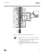
GUID-8A8C2683-25B1-4C7E-9CDE-5887825691BF V1 EN
Figure 439:
Typical TCC300 Stand-Alone External Connections
1. Motor voltage may be 120 or 240 V to neutral, or 240 V phase-to-
phase.
2. The customer is to provide an earth ground connection to the CT/
VT’s neutral connection, external to the control.
3. To Motor Power Seal-In board.
4. If the TCC300 is configured for the SCAMP pushbutton Auto/
Manual Switch type, then the Self
‑
Test Alarm relay is NOT
available.
1VAC388793-MB A
Section 8
Installation
TCC300
553
User Manual
Summary of Contents for TCC300
Page 1: ...Digital Tapchanger Control TCC300 User Manual ...
Page 2: ......
Page 3: ...Document ID 1VAC388793 MB Issued 2016 08 10 Revision A Copyright 2016 ABB All rights reserved ...
Page 26: ...20 ...
Page 34: ...28 ...
Page 91: ...1VAC388793 MB A Section 3 Operation TCC300 85 User Manual ...
Page 126: ...120 ...
Page 176: ...Section 4 1VAC388793 MB A TCC600 170 TCC300 User Manual ...
Page 260: ...254 ...
Page 328: ...322 ...
Page 494: ...488 ...
Page 556: ...550 ...
Page 580: ...574 ...
Page 600: ...594 ...
Page 700: ...694 ...
Page 710: ...704 ...
Page 712: ...706 ...
Page 713: ...707 ...
Page 714: ......
Page 715: ......

