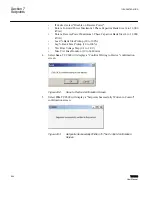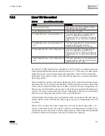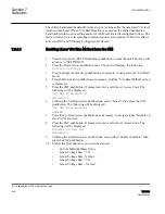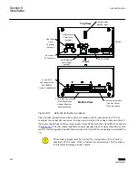
Open CT secondary will result in high voltage at CT terminals. Death,
severe injury or damage to equipment can occur.
Do not operate with CT secondary open. Short circuit or apply burden at
CT secondary during operation.
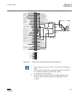
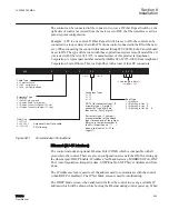
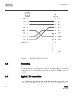
The communication ports provide remote access to the tapchanger control using the
TCC600® Communications Software.
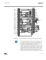
Pin 1 Voltage Input
This input accepts nominal 120 Vac, 60 Hz (or 50 Hz as ordered) to operate the control's
power supply and voltage sensing input. The acceptable voltage range for proper control
operation is from 90–140 Vac.
Power consumption is less than 8 VA. The input voltage is referenced to line neutral (Pin
3).
Control users may encounter situations where actuating the Drag Hands Reset pushbutton
on one of any of our adapter panels results in the loss of a Voltage Sense fuse. The Drag
Hands reset solenoid is powered from the circuit that powers the control, and provides the
control with sensing voltage. Initially, a 1/4 Ampere fuse was used in this circuit, and most
recently a 1 Ampere fuse was substituted to prevent further loss of the fuse. This
phenomenon is due to the fact that, as solenoids age, they may become sticky due to
mechanical misalignment, hardened grease, or shortened windings.
The adapter panels include a one ampere fuse in the voltage sense circuit. This value
should be adequate for all but the most extreme problems. When a Drag Hands Reset
Solenoid that consistently blows a one amp fuse is encountered, it is recommended that the
customer either remove the solenoid for cleaning and adjustment, or replace it completely.
Pin 2 Load Current Return
This is the non-polarity input to the load current measuring transformer. The companion
polarity input is Pin 4. The line current transformer input is isolated from other pins.
Pin 3 Neutral
This is the return for the Voltage Input (Pin 1), and n12 Vdc "wetting" voltage
(Pin 10).
Pin 4 Load Current Polarity
The line current input range is 0–640 mA (200 mA continuous) with 200 mA representing
the 1.0 per
‑
unit value. The measured current value is used for line drop compensation and
metering calculation.
Section 8
1VAC388793-MB A
Installation
556
TCC300
User Manual
Summary of Contents for TCC300
Page 1: ...Digital Tapchanger Control TCC300 User Manual ...
Page 2: ......
Page 3: ...Document ID 1VAC388793 MB Issued 2016 08 10 Revision A Copyright 2016 ABB All rights reserved ...
Page 26: ...20 ...
Page 34: ...28 ...
Page 91: ...1VAC388793 MB A Section 3 Operation TCC300 85 User Manual ...
Page 126: ...120 ...
Page 176: ...Section 4 1VAC388793 MB A TCC600 170 TCC300 User Manual ...
Page 260: ...254 ...
Page 328: ...322 ...
Page 494: ...488 ...
Page 556: ...550 ...
Page 580: ...574 ...
Page 600: ...594 ...
Page 700: ...694 ...
Page 710: ...704 ...
Page 712: ...706 ...
Page 713: ...707 ...
Page 714: ......
Page 715: ......


