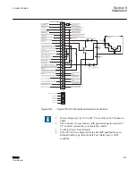
Pin 10 +12 Vdc Wetting Voltage
This is the output of an unregulated dc power supply internal to the control. It is referenced
to neutral and can supply up to 100 mA. It is used for powering the digital inputs of the
control through external relays. Depending on the voltage supplied to Pin 1 and loading,
its output can vary from +10 to +18 Vdc. It is not fused in the control.
Pins 11 & 12 Operations Counter Inputs 1 and 2
When "Input Selection 1" configuration is set to "Seal-In," the Counter
Input is used as the Switch Status Input and the Seal-In Input will cause the
counter to increment.
This digital input registers the counter contact closure. The pins are isolated from neutral
to permit placing the external contact in series with either the wetting voltage or neutral.
The operation count will increment when Pin 12 is grounded via the transformer or
regulator dry operation count switch.
This contact is needed for using the intertap time delay. Once the contact is opened, the
intertap time delay will begin counting down.
With the "Cam Follower" Operation Counter configuration, the Counter
Input is used for the Cam Follower contact input.
Pin 13 Input 1 - Motor Seal-In/Switch Status Input
When the Input Selection (1) screen in the Configuration menu is set to Seal-In Input, this
input will operate as a seal-in input and Counter Input. In this configuration, the digital
input is referenced to line neutral, but is unique in that it is configured to accept only the
output of the motor seal-in current detection transformer, from the B
‑
0553 motor seal-in
printed circuit board subassembly. The B
‑
0553 is a supplemental circuit board used in the
appropriate adapter panels.
When the Input Selection (1) screen in the Configuration menu is set to Switch Status
Input, this input will only operate as a switch status input. All seal-in input functions will
be disabled. In this mode, the switch status on the adapter panel can be read to determine
if it is in Auto or Manual ON/OFF. The status can be read through the seal-in/switch status
data point in the communications protocols.
Pins 14 & 15 Neutral Position Detector Inputs 1 and 2/ΔVAR2 (KeepTrack)
Disable Input
This input will only perform one function, either the Neutral Detect or the
ΔVAR2 (KeepTrack) Disable Input.
Section 8
1VAC388793-MB A
Installation
558
TCC300
User Manual
Summary of Contents for TCC300
Page 1: ...Digital Tapchanger Control TCC300 User Manual ...
Page 2: ......
Page 3: ...Document ID 1VAC388793 MB Issued 2016 08 10 Revision A Copyright 2016 ABB All rights reserved ...
Page 26: ...20 ...
Page 34: ...28 ...
Page 91: ...1VAC388793 MB A Section 3 Operation TCC300 85 User Manual ...
Page 126: ...120 ...
Page 176: ...Section 4 1VAC388793 MB A TCC600 170 TCC300 User Manual ...
Page 260: ...254 ...
Page 328: ...322 ...
Page 494: ...488 ...
Page 556: ...550 ...
Page 580: ...574 ...
Page 600: ...594 ...
Page 700: ...694 ...
Page 710: ...704 ...
Page 712: ...706 ...
Page 713: ...707 ...
Page 714: ......
Page 715: ......

