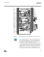
1. Motor voltage may be 120 or 240 V to neutral or 240 V phase to
phase.
2. The customer is to provide earth ground connection to CT/VT's
neutral connection, external to the control.
3. The self-test alarm and user-programmable alarm contacts are shown
in the de-energized state (no voltage applied). The self-test alarm
contacts open after the control passes the internal self-test.
4. The wiring from terminal 7 and 9 may or may not go directly to the
motor. Depending on installation, local codes and standards, the
wiring may go to interposing relay contacts, limit switch, seal-in
circuits, starters contactors, SCADA, test switches etc.
5. To isolate the load current, remove the jumper from TB1
‑
2 to TB1
‑
3.
6. For counter operation, connect TB2
‑
20 to neutral TB1
‑
3 through an
external dry contact. This connection is required for the intertap time
delay operation.
8.10
Typical regulator connection
illustrates an example of connections for a control with a Regulator Control
adapter panel. This example does not cover all situations. Motor Power and sensing
voltage can be obtained from a common source or from an independent source having a
nominal 120 Vac output. Normally, this is line-to-neutral voltage, although line-to-line
voltage can be used if recognition is made of any phase shift between the voltage and
current signals when using line drop compensation, to avoid introducing an unintentional
grounding into the control circuitry that could result in shorting a VT secondary. It is
strongly recommended that a 1:1 ratio isolation transformer of 25 VA or greater with
required voltage accuracy be used between the control and any line-to-line PT
connections. ABB has a suitable isolation transformer available in model M-0362. Please
consult factory for availability.
The current input to the TCC300 is rated at 0.2 A continuous, 0.4 A for two
hours, and 4.0 A for 1 second.
Load current must be reduced by an appropriate auxiliary transformer to 0.2 A "full scale"
before connecting to the adapter panel current inputs. Scaling factors may be chosen to
resemble 200 mA, 100 mA, or 5 A current transformers in readouts and current magnitude
settings. It is important that you obtain an application guide on an adapter panel specific
to your regulator application and follow those instructions.
Section 8
1VAC388793-MB A
Installation
568
TCC300
User Manual
Summary of Contents for TCC300
Page 1: ...Digital Tapchanger Control TCC300 User Manual ...
Page 2: ......
Page 3: ...Document ID 1VAC388793 MB Issued 2016 08 10 Revision A Copyright 2016 ABB All rights reserved ...
Page 26: ...20 ...
Page 34: ...28 ...
Page 91: ...1VAC388793 MB A Section 3 Operation TCC300 85 User Manual ...
Page 126: ...120 ...
Page 176: ...Section 4 1VAC388793 MB A TCC600 170 TCC300 User Manual ...
Page 260: ...254 ...
Page 328: ...322 ...
Page 494: ...488 ...
Page 556: ...550 ...
Page 580: ...574 ...
Page 600: ...594 ...
Page 700: ...694 ...
Page 710: ...704 ...
Page 712: ...706 ...
Page 713: ...707 ...
Page 714: ......
Page 715: ......

