1
2
5
6
9
10
11
12
15
18
19
20
21
22
23
29
30
32
33
34
51
M-2230
TB1
Auto Disable
Manual Lower
and Raise
Motor Return
Voltage Input
(Polarity)
Motor
M-2001
1
2
3
4
5
6
7
8
9
10
11
12
13
14
15
16
17
18
19
20
21
22
23
24
Voltage Input
(Polarity)
Load Current
(Return)
Neutral
Load Current
(Polarity)
Circulating Current
(Polarity)
Circulating Current
(Return)
Tapchanger Raise
Output
Motor Power Input
Voltage Reduction
Step #2 Input
Contact "Wetting"
12 V dc
Operation Counter
Input #1
Operation Counter
Input #2
Motor Seal-In Detector
Input
Neutral Position
Detector #1
Neutral Position
Detector #2
Tapchanger Lower
Output
Non-Sequential
Operation/Auto T.C.
Inhibit Input
Voltage Reduction
Step #1 Input
Motor Seal-In
Disconnect Output
User-Programmable
Alarm
Self-Test Alarm
User-Programmable
Alarm
Non-Interruptable
Power Supply Input
Self-Test Alarm
Voltage In
Fuse (1/4 A)
Motor Power Input
Manual
Auto
OFF
Neutral
Line Current
Return
Line Current 5.0 A
(Polarity)
Lower
Raise
Line Current 1.0 A
(Polarity)
Line Current 0.2 A
(Polarity)
Circulating Current 0.2 A
(Polarity)
Circulating Current 0.2 A
(Return)
(6 A
)
Programmable Alarm
Programmable Alarm
Volt Red #3
Volt Red #1
Volt Red #2
Counter
Neutral
CT
1
2
3
4
6
7
D1
D2
P2-1
P2-3
D4
D3
2
3
1
Manual
Auto
OFF
5
4
6
N/C
R1 1k-1 W
M-2001 Case
Ground Stud
M-2230
Ground Stud
D6
D5
F1
S1
60
Delta VAR2 Disable
GUID-D4596D9B-DF98-4326-B5D3-324055333160 V1 EN
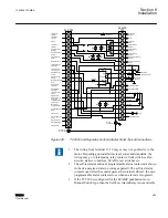
Figure 445:
TCC300 and Regulator Control Adapter Panel Typical Connections
1. The wiring from terminal 15-18 may or may not go directly to the
motor. Depending on installation, local codes and standards, the
wiring may go to interposing relay contacts, limit switch, seal-in
circuits, starters contactors, SCADA, test switches etc.
2. The self-test alarm and user-programmable alarm contacts are shown
in the de-energized state (no voltage applied). The self-test alarm
contacts open after the control passes the internal self
‑
test; the user-
programmable alarm contacts close when an alarm is recognized.
3. If the TCC300 is configured for the SCAMP pushbutton Auto/
Manual Switch type, then the Self
‑
Test Alarm Relay is not available.
1VAC388793-MB A
Section 8
Installation
TCC300
569
User Manual
Summary of Contents for TCC300
Page 1: ...Digital Tapchanger Control TCC300 User Manual ...
Page 2: ......
Page 3: ...Document ID 1VAC388793 MB Issued 2016 08 10 Revision A Copyright 2016 ABB All rights reserved ...
Page 26: ...20 ...
Page 34: ...28 ...
Page 91: ...1VAC388793 MB A Section 3 Operation TCC300 85 User Manual ...
Page 126: ...120 ...
Page 176: ...Section 4 1VAC388793 MB A TCC600 170 TCC300 User Manual ...
Page 260: ...254 ...
Page 328: ...322 ...
Page 494: ...488 ...
Page 556: ...550 ...
Page 580: ...574 ...
Page 600: ...594 ...
Page 700: ...694 ...
Page 710: ...704 ...
Page 712: ...706 ...
Page 713: ...707 ...
Page 714: ......
Page 715: ......


