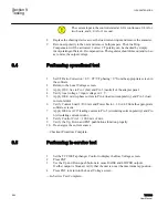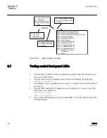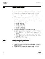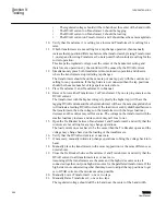
Do not reverse the ground and hot wires when connecting an
external source.
3.
Apply motor auxiliary voltage to Pin 8 (motor power input) and Pin 3 (neutral).
4.
Verify that the motor runs in the proper direction when conditions of sensed voltage
result in activation of Raise and Lower outputs.
In no case should the load current circuit be interrupted with the
regulator or transformer energized.
Do not remove auxiliary current transformers without shorting the
current inputs. Death or severe electrical shock can occur.
5.
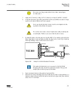
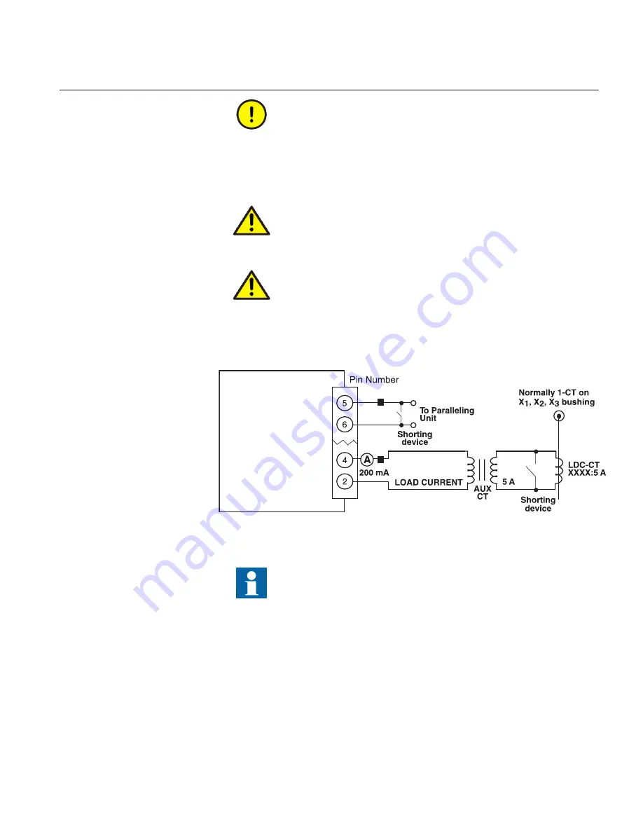
Temporarily place a shorting device across the LDC
‑
CT secondary to short the line
drop compensator circuit, and place another shorting device to short the circulating
current paralleling output, for the load current check.
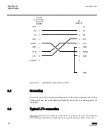
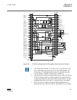
TCC300
GUID-F089369B-3201-4640-AD12-8D5EABD63406 V1 EN
Figure 449:
Setup for Current Checkout Procedure
Pin numbers indicated above are accurate for the M
‑
2050B
Mounting Kit only; check the Application Guide of the specific
adapter panel used for proper pin numbers.
6.
Insert an ammeter between the polarity input and Pin 4.
7.
Open the load current shorting device and with a known load on the transformer or
regulator, measure the current in the load current circuit to ensure that this current is
correct for 0.2 A full load.
1VAC388793-MB A
Section 9
Testing
TCC300
579
User Manual
Summary of Contents for TCC300
Page 1: ...Digital Tapchanger Control TCC300 User Manual ...
Page 2: ......
Page 3: ...Document ID 1VAC388793 MB Issued 2016 08 10 Revision A Copyright 2016 ABB All rights reserved ...
Page 26: ...20 ...
Page 34: ...28 ...
Page 91: ...1VAC388793 MB A Section 3 Operation TCC300 85 User Manual ...
Page 126: ...120 ...
Page 176: ...Section 4 1VAC388793 MB A TCC600 170 TCC300 User Manual ...
Page 260: ...254 ...
Page 328: ...322 ...
Page 494: ...488 ...
Page 556: ...550 ...
Page 580: ...574 ...
Page 600: ...594 ...
Page 700: ...694 ...
Page 710: ...704 ...
Page 712: ...706 ...
Page 713: ...707 ...
Page 714: ......
Page 715: ......


