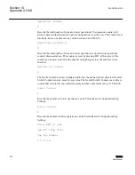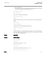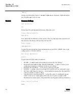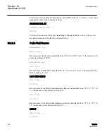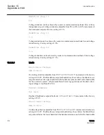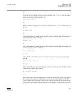
•
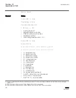
Q (P
[5]
/O
[3]
) = RTN Fail
•
R (Q
[5]
/P
[3]
) = Ind Tap Wear
•
S (R
[5]
/Q
[3]
) = Op Count Signal
•
T (S
[5]
/R
[3]
) = Tap Changer Fail
Alarm Status Key
•
1 Alarm Enabled/Condition Met
•
0 Alarm Enabled/Condition Not Met
•
X Alarm Disabled/Condition Met
•
- Alarm Disabled/Condition Not Met
Press ENT to view
Input Status
C NS VR TC KT N MS
00 00 – – 0 RL 0 0
•
C = Counter Contact
•
NS = Non-Sequential Input
•
VR = Voltage Reduction Inputs 1 and 2
•
TC = Tap Connection
•
KT = Keeptrack Lower and Raise Input
•
N = Neutral Tap Position MS = Motor Seal-In
Key
•
1 = True (on)
•
0 = False (off)
Press ENT to view
Output Status
RAISE LOWER ALARM
1 0 0
•
RAISE Raise Contact
•
LOWER Lower Contact
•
ALARM Alarm Contact
Key
1VAC388793-MB A
Section 10
Appendix A HMI
TCC300
609
User Manual
Summary of Contents for TCC300
Page 1: ...Digital Tapchanger Control TCC300 User Manual ...
Page 2: ......
Page 3: ...Document ID 1VAC388793 MB Issued 2016 08 10 Revision A Copyright 2016 ABB All rights reserved ...
Page 26: ...20 ...
Page 34: ...28 ...
Page 91: ...1VAC388793 MB A Section 3 Operation TCC300 85 User Manual ...
Page 126: ...120 ...
Page 176: ...Section 4 1VAC388793 MB A TCC600 170 TCC300 User Manual ...
Page 260: ...254 ...
Page 328: ...322 ...
Page 494: ...488 ...
Page 556: ...550 ...
Page 580: ...574 ...
Page 600: ...594 ...
Page 700: ...694 ...
Page 710: ...704 ...
Page 712: ...706 ...
Page 713: ...707 ...
Page 714: ......
Page 715: ......


