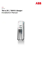
background image


MANUAL


Terra 54 / 54HV charger


Installation Manual


Summary of Contents for Terra 54 Series

Page 1: ... MANUAL Terra 54 54HV charger Installation Manual ...

Page 2: ...erty in the ABB products described in this document The information in this document is subject to change without notice and should not be construed as a commitment by ABB ABB assumes no responsibility for any errors that may appear in this doc ument In no event shall ABB be liable for direct indirect special incidental or consequential damages of any nature or kind arising from the use of this do...

Page 3: ...taining the Terra 54 12 2 2 2 Ventilation and airflow of the Terra 54 12 2 2 3 Bollards 13 2 3 Electrical engineering 14 2 3 1 Requirements External RCD 14 2 3 2 Conductor and cable diameter 15 3 Site design 17 3 1 Cable reach 17 3 2 Different alignment possibilities 17 4 Site construction 19 4 1 About construction 19 4 2 Power feed 19 4 3 Construct foundation 19 4 3 1 Placement on soil 19 4 3 2 P...

Page 4: ...ect cables 28 5 6 1 Connect PE of power cable 28 5 6 2 Connect power cable 29 6 Commissioning 32 6 1 Commissioning preparation 32 7 Cleaning of the cabinet 34 7 1 Cleaning of the cabinet 34 8 Technical Data 35 8 1 Electrical data 35 8 2 Mechanical data 36 8 3 Environment 36 8 4 Certifications 37 9 Contact information 38 10 Appendix A Concrete foundation 39 10 1 Terra 53 54 drawing 39 11 Appendix B...

Page 5: ...f the charger OCPP Open Charge Point Protocol Open standard for communication with charge stations PE Protective Earth PPE Personal Protective Equipment Equipment such as safety shoes helmet glasses gloves RCBO Residual current Circuit Breaker with Overload protection Breaks the connection if a residual current or overload is detected RCD Residual Current Device Breaks the connection if a residual...

Page 6: ...pes The different ver sions are described in a separate paragraph 1 2 Intended document users This document is intended to be used by Customers who purchased a Terra 54 or are in the process of ordering and want to know in more detail how it has to be installed Contractors who are responsible for site preparation and or installation of a Terra 24 or Terra 54 1 3 Similarities and differences betwee...

Page 7: ...dard J CHAdeMO standard G AC connector 22 43 kW T AC Socket 22 kW HV High Voltage 1 5 Signs The following signs are used on the equipment and in this manual DANGER Hazardous voltage Identifies a hazard that could result in severe injury or death through electrocution WARNING Various Identifies a hazard that could result in severe injury or death WARNING Rotating parts Identifies a hazard that coul...

Page 8: ...arge station and for the coordination of all work The owner is cautioned that changes or modifications not expressly approved by ABB could void the owner s authority to operate the equipment and ABB s war ranty policy Neither ABB nor its affiliates shall be liable to the purchaser of this product or third parties for damages losses costs or expenses incurred by purchaser or third parties as a resu...

Page 9: ...electrical power is disconnected from the system 3 Only ABB certified technicians are permitted to commis sion the Terra 4 When the system is in an open or dangerous condition do not allow unqualified persons to go near it Instruct and warn people about the potential harmful high voltages 5 The installation and maintenance personnel must supply their own lighting equipment since the T54 has no lig...

Page 10: ...cription of the product 2 1 Overview of the system 2 1 1 Complete overview Example of a complete installation A Power distribution board of the owner B Cables in cable conduit if required C Terra 54 D Parking space for charging E Electric vehicle ...

Page 11: ... Charge outlet DC connector and DC cable B Emergency stop F Air inlet C Display HMI G Border cover D RFID card reader H Air outlet backside 2 1 3 Inside view A Cable gland plate D Main switch B PE connection E Power connections C Door switch 2x on front door 1x on each side door ...

Page 12: ...x D x H 565 x 780 x 1900 mm Front side 600 mm in order to open the front door Left and right side 510 mm in order to open left and right door Backside 100 mm in order to guarantee an unimpeded airflow 2 2 2 Ventilation and airflow of the Terra 54 The Terra 54 has an air inlet on the right side and outlet on the back side NOTICE Free air flow If necessary take precautions to prevent snow or objects...

Page 13: ...TERRA 54 54HV CHARGER 2018 10 03 13 40 2 2 3 Bollards It is advised to place bollards around the charger to protect the charging station against cars hitting and damaging the cabinet ...

Page 14: ...ty com ponents inside the charger is shown in the figure below 2 3 1 Requirements External RCD NOTICE External RCD not included in delivery scope Upstream RCD s are explicitly excluded from ABB s delivery scope and belong to the scope of the installation company The locally certified installation company can base the RCD device type amongst other external factors on below charger characteristics I...

Page 15: ... tion of the charger we give you the advice to select an RCD that has proven to be able to with stand these short current peaks high immunity As a suggestion to the installation company ABB recommends the following RCD type which will work in most grid situations 1 ABB make F204 B S 125 0 3 code 2CSF204823R3950 It is the responsibility of your installation company to select the right device Local ...

Page 16: ...TERRA 54 54HV CHARGER 2018 10 03 16 40 Example of cable lug to be used ...

Page 17: ...AC cable leaves on the left side The cables and the connectors mounted on the cables are different for each charging standard and make them more or less flexible to reach out The figure below shows the charger in the center with each type of connector and how far it can reach out The yellow circle describes the range of the Combo cable green circle the CHAdeMO cable blue circle the AC cable 3 2 Di...

Page 18: ...CHARGER 2018 10 03 18 40 This makes some positions of the charger with respect to the parking space more favorable than others Please keep this in mind when designing a site Some possible situations are showed below ...

Page 19: ...pe of surface where the Terra 54 will be installed 4 3 1 Placement on soil There are 2 options when the charger is placed on soil 1 Use a prefab concrete foundation to get a firm fixation on soil A prefab concrete foundation can be ordered separately or produced locally accord ing the specifications 2 The construction of a custom built foundation Depending on the situation and cable type the cable...

Page 20: ...internal routing in the cabinet 4 4 Power cable Cable type 3P N PE shielded cables are optional if required by local law Optional cable shielding must be attached to the PE Rail at both ends of the cable The diameter of the cable conductor must be determined by your contractor elec trician The maximum diameter surface of the cable conductor is 95 mm The PE conductor of the power cable must have th...

Page 21: ...ommended minimum bandwidth upload 128 kb s download 4 Mmb s Recommended availability 99 9 The connection must be available for the ABB service engineer and the NOC Please contact ABB for a specific configuration In case the separate internet connection is not used please assure the cable entry hole is closed to assure the IP54 grade of the cabinet and prevent insects and small animals to en ter th...

Page 22: ...ken or tilted The cabinet is equipped with Shockwatch and Tiltwatch indicators Checking the Shockwatch and TiltWatch PLUS sensors If the ShockWatch indicator is red or the TiltWatch PLUS indicator is tilted over 30 1 Do not refuse the delivery receipt 2 Make a notation on the delivery receipt and inspect cabinet for damage 3 If damage is discovered leave cabinet in original package and request imm...

Page 23: ...rap 2 Remove the plastic protection profiles 3 Remove the innerside shrink wrap 5 2 2 Mounting preparations Remove border covers Preconditions Tools Allen key size 4 1 Remove the bolts C of the border covers 2 Remove the U shaped covers A B off the base of the Terra 54 ...

Page 24: ...rnet cable if required 7 Put the cable gland s in a safe location It they will be re installed later 8 Close the doors starting with the side door and subsequently the front door 9 Remove the nuts A at the four corners 5 3 Move cabinet to position 5 3 1 Options There are two options to move the Terra 54 from the delivery truck to the location Move cabinet with hoist on Page 25 Move cabinet with fo...

Page 25: ... the cabinet to its position is not con sidered a warranty issue 5 3 2 Move cabinet with hoist A Swivel eye bolts B Lifting loops C Hoisting equipment Preconditions Use swivel eye bolts A or bolts with lifting loops B 1 Insert and tighten the bolts A or B at opposite corners 2 Connect the hoisting equipment C 3 Move the Terra 54 carefully to its location WARNING Various Keep the hoisting angle bel...

Page 26: ...ully to its location 5 4 Mounting the cabinet Preconditions Tools Spanners size 17 The Terra 54 is about 0 5 m above its location Open the front door and right side panel Guide the power cable through the cable gland and if required the Ethernet cable through the smaller gland 5 4 1 Mounting the cabinet to a foundation Placement on a concrete foundation A Foundation B Terra 54 ...

Page 27: ...3 Install cable gland s The maximum diameter of the grid cable is 45 mm The minimum diameter of the grid cable is 34 mm with the standard fitted cable gland insert Use foam or shrinking glands to close the remaining holes to prevent insects and small ani mals to enter the cabinet 1 Slide the cable gland s over the cable s 2 Push the cables back through the gland plate until sufficient cable length...

Page 28: ...ver B against the back of the Terra 54 2 Put the U shaped cover A on the base of the Terra 54 from the front The U shaped cover overlaps the sides of the small cover 3 Insert and tighten the bolts C at both sides 5 6 Connect cables 5 6 1 Connect PE of power cable Preconditions Tools Wire stripper pliers wire end lug pliers wire end lug DANGER Hazardous voltage Make sure that the main switch of the...

Page 29: ...rs to remove 20 mm of the insulation from the end of the PE wire 3 Attach a cable lug to the end of the PE wire 4 Loosen the bolt of the PE connector 5 Attach the PE wire onto the PE connector 6 Tighten the bolt 5 6 2 Connect power cable Preconditions Tools Wire stripper pliers wire end lug pliers wire end lugs DANGER Hazardous voltage Make sure that the main switch of the power supply group for t...

Page 30: ...e four wires onto their connectors From left to right L1 brown at position 2 L2 black at position 4 L3 grey or black at position 6 0 blue at position 8 6 Tighten the bolts The advised torque value ranges between 15 and 20 Nm 7 Install the covers back onto the connector WARNING Leave the main switch switched off The Terra 54 is not ready for use yet Please contact the ABB Service department at leas...

Page 31: ...ight 1 Cut the network cable to the correct length to reach the Ethernet connector The connector is located behind the right side door near the bottom of the charger 2 Use network cable pliers to install an RJ45 connector on to the network cable 3 Insert the RJ45 connector into the Ethernet connector ...

Page 32: ...ic vehicle must be available for testing AC charging Any electric vehicle for instructing the site operator NOTICE Warranty It is not allowed to move the Terra 54 after it is commis sioned In case the Terra 54 is moved without approval from ABB the warranty will be considered void In case of relocation please contact the local ABB Service department Commissioning is executed according to the Check...

Page 33: ...ocument A4 on the page of the charger in PDF Change Deliver status to SAT After completing the Site Acceptance Test ABB s Network Operation Center will be triggered to perform a final check on the connection and configuration of the charger Upon approval the charger will be operational and initialized for use ...

Page 34: ...e dirt by hand with a non woven nylon hand pad Rinse thoroughly with tap water Optionally apply wax on the front for extra protection and gloss Do a check on the coating for damage NOTICE When the Terra 54 Charge Station is exposed to rain it is sufficient to clean it twice a year CAUTION Do not apply high pressure water jets Water may leak into the Terra 54 Charge Station If a high pressure water...

Page 35: ...put current 125 A DC 5 CCS 2 DC output C HV Maximum output power 50 kW Output voltage range 200 950 V DC CCS 2 Maximum output current 125 A DC 5 CCS 2 DC output J Maximum output power 50 kW Output voltage range 200 500 V DC CHAdeMO Maximum output current 120 A DC CHAdeMO DC output J HV Maximum output power 50 kW Output voltage range 200 950 V DC CHAdeMO Maximum output current 120 A DC CHAdeMO Opti...

Page 36: ...Network connection GSM CDMA modem 10 100 Base T Ethernet 8 2 Mechanical data Mechanical data Dimensions H x W x D 1900 mm x 565 mm x 780 mm Weight 325 kg Volume 0 76 m3 Dimensions including packaging H X W x D 2100 mm x 1200 mm x 800 mm Weight including packaging 350 kg Weight concrete foundation 400 kg Mechanical impact protection IK08 Housing Stainless steel 430 8 3 Environment Environmental dat...

Page 37: ...itude 2000 m max 8 4 Certifications CE Certification EMC EN 61000 6 3 Class B emission EN 61000 6 2 immunity see certificate LVD IEC 61851 1 IEC 62196 IEC 60950 EN 61010 EN 60335 see certificate RFID ISO IEC 14443 A B ISO IEC15693 ISO 18902 NFC ...

Page 38: ...ervice organization or Service partner for first line problem analysis and solving In case they cannot solve the problem they will contact the second line Service organization ABB EV Infrastructure Delftweg 65 2289 BA Rijswijk The Netherlands Phone 31 0 70 3076200 2nd Line support 31 0 70 3076201 www abb com evcharging ...

Page 39: ...TERRA 54 54HV CHARGER 2018 10 03 39 40 10 Appendix A Concrete foundation 10 1 Terra 53 54 drawing ...

Page 40: ...TERRA 54 54HV CHARGER 2018 10 03 40 40 11 Appendix B Disposal instruction 11 1 Directive on Waste Electrical and Electronic Equipment WEEE 2012 19 EU ...

Reviews: