background image

19

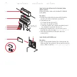
Procedure

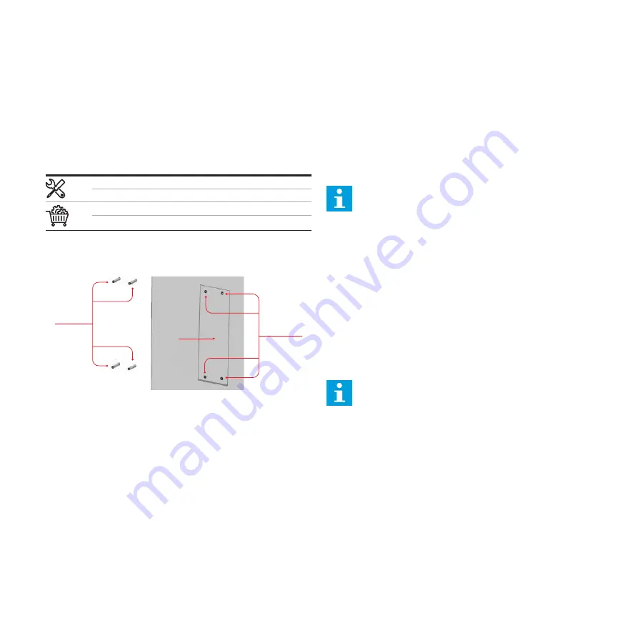
1. Hold the installation template (A) against the wall.
2. Make sure that the installation is level. Use the spirit level.
3. Mark the location for the mounting holes (B).
4. Drill the mounting holes (B).

Note: 

For the diameter of the holes, refer to 

chapter 

Technical data, page 32

 and section 

Required ools for installation, page 16.

5.  Insert the anchores for the mounting holes (C) in the 

mounting holes.

General mechanical installation procedure

Note: 

The mounting screws and Anchors that are 

included in the delivery are serviceable for a brick 
wall. If you want to mount the EVSE on a different 
type of wall, contact your local representative of 
the manufacturer, refer to section 

Manufacturer 

and contact data

 at the end of the document.

Prepare the holes for the mounting screws

Spirit level
Drill
Installation template

Anchors for the mounting holes

Table 16: Preliminary requirements

A

B

C

Mechanical installation
TA B L E  O F  CO N T EN T S

P R E V I O US  C H A P T ER

N E X T  C H A P T ER

Summary of Contents for Terra AC wallbox UL

Page 1: ... INSTALLATION MANUAL Terra AC wallbox UL 40 80 A ...

Page 2: ...e EVSE Safety instructions for earthing Special safety instructions Additional important safety instructions 09 15 Description Intended use External components Product label LED indicators Display for display models only Internal components 16 17 Installation In the box Required tools for installation General installation procedure Unpack the EVSE 18 Site preparation Select the site Prepare the si...

Page 3: ...Insert the Ethernet conduit Insert and connect the Ethernet cable Insert the smart meter communication conduit Insert and connect the wires for the smart meter communication Insert the Nano M2M SIM card Rotary switch set current limit 28 Commissioning General commissioning procedure Energize the EVSE Set up the EVSE TerraConfig app to do the commissioning 29 31 Troubleshooting Troubleshooting proc...

Page 4: ...ruction this can cause damage to the EVSE or to property Note A note gives more data to make it easier to do the steps for example Information about the condition of the EVSE before you start the procedure Requirements for personnel for a procedure General safety instructions for a procedure Information about spare parts that are necessary for a procedure Information about support equipment that i...

Page 5: ... the manufacturer to do a remote check on the correct operation of the EVSE Cabinet Enclosure of the EVSE including the components on the inside Contractor Third party that the owner or site operator hires to do engineering civil and electrical installation work Grid provider Company that is responsible for the transport and distribution of electricity Local rules All rules that apply to the EVSE ...

Page 6: ...gainst any kind of security breaches unauthorized access interference intrusion leakage and or theft of data or information The manufacturer is not liable for damages and or losses related to such security breaches any unauthorized access interference intrusion leakage and or theft of data or information Required qualifications for the installation engineer The qualified installation engineer full...

Page 7: ...d used in accordance with the instructions may cause harmful interference to radio communications However there is no guarantee that interference will not occur in a particular installation If this equipment does cause harmful interference to radio or television reception which can be determined by turning the equipment off and on the user is encouraged to try to correct the interference by one or...

Page 8: ...Insert the AC input conduit page 22 For the torque requirements for the screws of the terminal block for the AC power refer to chapter Technical data page 34 SAVE THESE INSTRUCTIONS Note It is possible that not all symbols are present on the EVSE Discard the EVSE or parts of the EVSE Incorrect waste handling can have a negative effect on the environment and human health due to potential hazardous ...

Page 9: ...r Technical data page 32 Only use the EVSE with accessories that the manufacturer provides or that obey the local rules The EVSE AC input is intended for a hardwired installation that complies with the applicable national regulations Danger General risk If you use the EVSE in any other way than described in the related documents you can cause death injury and damage to property Use the EVSE only a...

Page 10: ...us of the EVSE and the charge session E RFID reader To authorize the start or stop of a charging session with an RFID card F LED indicators To show the status of the EVSE and the charge session G Holster inlet To store the charge connector H Conduit enclosure plug For the AC input cable I Conduit enclosure plug For the Ethernet cable J Conduit enclosure plug For the smart meter connections K Charg...

Page 11: ... D Product model number E Barcode with the serial number of the EVSE F Barcode with the part number of the EVSE G Power rating of the EVSE NEMA enclosure type ambient temperature H Mass of the EVSE I Address of the manufacturer J Reference to the manual K Certification A B C D E F G I K H J Product label TABLE OF CONTENTS PREVIOUS CHAPTER NEXT CHAPTER ...

Page 12: ... No car connected Flashing A car is connected waiting for authorization Internet connection LED On Connected to the internet Off Not connected to the internet Flashing The internet connection is set up EVSE on off LED On The EVSE is on Off The EVSE is off Flashing The EVSE is in setup Table 9 LED indicators and statuses Error LED RFID Charging LED Cable and car detection and car authorization LED ...

Page 13: ...28 02 2022 08 17 AM 28 02 2022 11 16 AM 55 122 kWh 02 59 02 28 2022 11 16 AM Start and end time Energy delivered and duration of the charge session Charging completed screen Display wakeup functionality via touch or when changing charge status connect or disconnect cable to EV preparing to charge and charging Screen dim time 2 minutes default value Screen dim time range 10 300 seconds Screen brigh...

Page 14: ... Disconnect the charge cable and connect it again Total 080 378 kWh SN TACW1945021P4609 02 28 2022 11 16 AM 0x0010 v 1 5 2 Error code Contact your service provider Total 080 378 kWh SN TACW1945021P4609 02 28 2022 11 16 AM v 1 5 2 The EV is not ready for the charge session TABLE OF CONTENTS PREVIOUS CHAPTER NEXT CHAPTER ...

Page 15: ...agement makes sure that the available capacity of the building or home is not exceeded A number of devices share a grid connection that has a maximum capacity The total power demand of the devices that use the grid connection must not exceed the grid capacity The load management feature prevents that the system exceeds the grid capacity and prevents damage of the fuses At times when the current de...

Page 16: ...iver Philips P3 screwdriver Elements Number of copies EVSE 1 QSG ABB Terra AC Wallbox Ready Set Charge 1 RFID card 1 Installation template 1 Anchors 0 39 x 3 14 in 10 x 80 mm 4 Screws 0 23 x 2 95 in 6 x 75 mm with silicone washer 4 Mechanical lug 2 Cold pressed ring terminal L1 L2 2 Cold pressed ring terminal PE 1 0 23 x 0 314 in 6x8 mm screw 3 L1 L2 cover 1 In the box Required tools for installat...

Page 17: ...age 21 5 Install the cabinet cover 6 Do the commissioning procedure Refer to chapter General commissioning procedure page 28 Unpack the EVSE 1 Open the box 2 Take out the EVSE and including parts like QSG from the box 3 Remove all packaging material from the EVSE 4 Discard the packaging material 5 Make sure that all parts are delivered according to the order Refer to the order and section In the b...

Page 18: ... power supply is available For the power supply specifications refer to chapter Technical data page 32 3 Obey the space requirements Refer to Table 12 Space requirements for installation on this page Z1 Z2 EVSE Parameter Specification in mm Z1 8 200 Z2 indoor use 18 to 48 450 to 1200 Z2 outdoor use 24 to 48 600 to 1200 Table 12 Space requirements for installation Parameter Specifications Wall thic...

Page 19: ...n the mounting holes General mechanical installation procedure Note The mounting screws and Anchors that are included in the delivery are serviceable for a brick wall If you want to mount the EVSE on a different type of wall contact your local representative of the manufacturer refer to section Manufacturer and contact data at the end of the document Prepare the holes for the mounting screws Spiri...

Page 20: ...nchors For the specification refer to chapter Technical data page 32 Move the holster inlet Step 1 Step 2 A Procedure 1 Remove 2 screws and remove the front cover 2 Remove 11 screws and remove the maintenance door 3 Remove the screw A on the left side of socket 4 Move the holster inlet away TABLE OF CONTENTS PREVIOUS CHAPTER NEXT CHAPTER ...

Page 21: ...x page 16 Mounting screws Smart meter with ModBus RTU interface Wire for RS485 Ethernet cable AC input cable 1 phase AC input conduit Table 21 Preliminary requirements Procedure 1 Install the AC input conduit and cable by inserting and connecting them 2 Install the Ethernet conduit and cable by inserting and connecting them 3 If necessary install for the smart meter communication conduit and cable...

Page 22: ... B A A Insert the AC input cable and install the cold pressed terminal for PE Procedure 1 Strip the PE wire For the specification refer to chapter Technical data page 32 2 Insert the PE wire into the cold pressed terminal to its full insertion length Crimp the cold pressed terminal with the correct jaws 3 Finished 1 2 mm 0 1 mm TABLE OF CONTENTS PREVIOUS CHAPTER NEXT CHAPTER ...

Page 23: ...rews A to the correct torque For the specification refer to chapter Technical data page 32 1 2 mm 0 1 mm Install the cold pressed terminal for L1 L2 option 2 Procedure 1 Strip the wires For the specification refer to chapter Technical data page 32 2 Insert the wire into the cold pressed terminal to its full insertion length Crimp the cold pressed terminal with the correct jaws 3 Finished 1 2 mm 0 ...

Page 24: ...the specification refer to chapter Technical data page 32 3 Install the protect cover E Insert the Ethernet conduit Procedure 1 Remove the conduit enclosure plug A from the EVSE 2 Put the Ethernet conduit B through the cable inlet hole 3 Install the Ethernet conduit A A B A Earthing wire B L2 AC input wire C L1 AC input wire D Screws E Protect cover TABLE OF CONTENTS PREVIOUS CHAPTER NEXT CHAPTER ...

Page 25: ...ocket B Refer to section Internal components page 15 2 Connect the Ethernet cable either to a PC router or gateway or to the previous EVSE in a chain C 3 If you connect EVSEs in a daisy chain put the RJ45 plug of Ethernet cable to the next EVSE D in the secondary Ethernet RJ45 socket E B C E D A A A B Insert the smart meter communication conduit 1 Remove the conduit enclosure plug A from the EVSE ...

Page 26: ...a Connect the positive wire C b Connect the negative wire D c If the smart meter has a common isolated ground for shielded wire connect the wire E 3 Tighten the screws to the correct torque For the specification refer to chapter Technical data page 32 4 Install the terminal block connector B on the connector A Insert and connect the wires for the smart meter communication Connect the smart meter w...

Page 27: ... to different number for different current limit Rotary switch set current limit B A Position of switch Current limit 0 80 A 1 64 A 2 56 A 3 48 A 4 40 A 5 32 A 6 24 A 7 16 A 8 10 A 9 Not used switch limit will be invalid 0 1 2 3 4 5 6 7 8 9 TABLE OF CONTENTS PREVIOUS CHAPTER NEXT CHAPTER ...

Page 28: ...ou work with electricity The power supply comes on A series of self checks start to make sure that the EVSE works correctly and safely If the EVSE detects a problem the error LED comes on 4 Open the TerraConfig app 5 Enter the PIN 6 Do these steps on the TerraConfig app a Update the product firmware Do this step again until the TerraConfig app does not detect newer firmware b Adjust the parameter ...

Page 29: ...ltage from the grid is not more than specified Under voltage 0x0010 The voltage on the power input is not sufficient Make sure that the voltage from the grid is not less than specified Over current 0x0020 There is an overload on the EV side Examine the EV charge cable connection Connect the EV charge cable correctly Severe over current 0x0040 There is an overload on the EV side Examine the EV char...

Page 30: ...us communication is lost Do a check on the connection of the wires and the polarity Do a check if all addresses are unique Do a check if the baud rate is the same as the other device or meter Do a check if the parity value of the other device or meter agrees with the EVSE None Do a check if the stop bit and data bit are the same on the other device or meter Offline charging record reaches memory l...

Page 31: ...e EV charge cable If necessary connect the EV charge cable There is a problem with the ChargerSync app or the RFID card Make sure that the user has registered in the ChargerSync app Make sure that you use a RFID card that the manufacturer provided Make sure that the RFID card is added on the ChargerSync app Start the ChargerSync app Start the authorization process De energize the EVSE 1 Open the b...

Page 32: ...age integrated surge protection Ground fault circuit interrupter Integrated 20 mA AC CCID no addiontal required Overvoltage category III Energy metering Revenue grade energy meter Class B 2 Rotary switch set current limit options 80 A model 10 A 16 A 24 A 32 A 40 A 48 A 56 A 64 A 80 A Rotary switch set current limit options 40 A model 10 A 16 A 24 A 32 A 40 A Stand by mode power consumption 3 W 5 ...

Page 33: ...tems Android 4 4 or higher iOS8 or higher RFID ISO IEC 14443A MIFARE Classic 1K and 4K memory Available configurable contacts 1 input 1 output Configurable output contact rated load 250 VAC or 30 VDC max current 1 A User interface User authentification ABB RFID card 1 included or ChargerSync app or portal User interface Installer interface ChargerSyncTM app or portal TerraConfig app and portal for...

Page 34: ...ons AC input mechanical lug Strip length 0 55 in 14 mm supported range 8 2 AWG 8 36 35 mm AC input cold pressed ring terminal 80A Strip length 0 55 in 14 mm 2 AWG 35 mm AC input cold pressed ring terminal 40A Strip length 0 55 in 14 mm 6 AWG 13 mm PE cold pressed ring terminal Strip length 0 33 in 8 5 mm 8 AWG 8 36 mm Terminal block external meter input and output Strip length 0 19 in 5 mm support...

Page 35: ...tions Dedicated upstream protection device s Breaker EVSE internal Ground Fault Protection 20 mA AC Upstream overcurrent protection breaker Breaker rating see table above Tripping characteristics type C Circuit breaker rating Note Consult with a licensed contractor licensed electrician or trained installation expert to ensure compliance with local building and safety standards Note The breaker val...
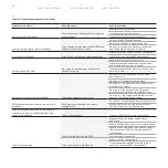
Page 36: ...t cover non display no ABB logo UL 40 80 A 2 screws included SER Front cover non display models no ABB logo UL 40 80 A ABB6AGC109709 Front cover display no ABB logo UL 40 80 A 2 screws included SER Front cover display models no ABB logo UL 40 80 A ABB6AGC109714 Front cover non display UL 40 80 A 2 screws included SER Front cover non display UL 40 80 A ABB6AGC109717 Front cover display models UL 40...

Page 37: ...etherlands Contact data The local representative of the manufacturer can give you support on the EVSE You can find the contact data here https emobility abb com Copyright 2022 ABB All rights reserved Specifications subject to change without notice Rev A March 2022 ...

Reviews: