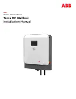
background image


MANUAL: NORTH AMERICA


Terra DC Wallbox 


Installation Manual


Summary of Contents for Terra DC wallbox

Page 1: ... MANUAL NORTH AMERICA Terra DC Wallbox Installation Manual ...

Page 2: ...ty in the ABB products described in this document The information in this document is subject to change without notice and should not be construed as a commitment by ABB ABB assumes no responsibility for any errors that may appear in this document In no event shall ABB be liable for direct indirect special incidental or consequential damages of any nature or kind arising from the use of this docum...

Page 3: ...nection 14 3 2 Electrical requirements 15 3 2 1 Required electrical grid configuration 15 3 2 2 Overcurrent protection device 17 3 2 3 Conduit for power input wires 17 3 2 4 Specification for power input wires 17 3 2 5 Conduit for ethernet cable 18 3 2 6 Specification for ethernet cable 18 3 3 DC Wallbox placement 18 3 3 1 Charging cable reach 18 3 3 2 DC Wallbox position with respect to parking s...

Page 4: ...nnect PE of power cable 33 5 5 2 Connect power cable 34 6 Commissioning 36 6 1 Commissioning preparation 36 7 Maintenance and Cleaning of the cabinet 37 7 1 Recommended Periodic maintenance 37 7 2 Cleaning of the cabinet 37 8 Technical Data 38 8 1 Electrical data 38 8 2 Mechanical data 39 8 3 Environment 39 8 4 Certifications 39 9 Contact information 40 10 Appendix A Mounting points 41 10 1 Terra ...

Page 5: ...ct functioning of the charger Owner The legal owner of the charger OCPP Open Charge Point Protocol Open standard for communication with charge stations PE Protective Earth PPE Personal Protective Equipment Equipment such as safety shoes helmet glasses gloves RCD Residual Current Device Breaks the connection if a residual current is detected RFID Radio Frequency IDentification RFID is a communicati...

Page 6: ...de carefully and attentively Be sure to follow all instructions when installing the charger ABB is not responsible for any damage caused by not following or incorrectly executing the instructions described in this manual 1 2 Intended document users This document is intended to be used by Customers who have purchased a Terra DC Wallbox or customers in the process of ordering and require additional ...

Page 7: ...harging cable type ABB order code CCS 1 ABB6AGC076604 CHAdeMO ABB6AGC076601 1 4 Signs The following signs are used on the equipment and in this manual DANGER Hazardous voltage Identifies a hazard that could result in severe injury or death through electrocution WARNING Various Identifies a hazard that could result in severe injury or death ...

Page 8: ...ing out installation or maintenance work Write an emergency plan that instructs people what to do in case of emergency Prepare the site where the charge station will be installed according to the requirements described in this guide Ensure there is sufficient space around the charger to carry out maintenance work Appoint a person responsible for the safe operation of the charge station and for the...

Page 9: ...not drop the Terra DC Wallbox 1 4 3 Sharp edges WARNING Sharp metal edges There could be sharp metal edges inside the Terra DC Wallbox It is recommended to wear mash protecting gloves when working inside the charger 1 4 4 Electric hazards DANGER Hazardous voltage The Terra DC Wallbox contains conductors under hazardous electrical voltages The grid terminals on the internal DIN rail may carry hazar...

Page 10: ...rous condition do not allow unqualified persons to go near it Instruct and warn people about the potentially harmful high voltages 5 The installation and maintenance personnel must supply their own lighting equipment because the Terra DC Wallbox has no lights inside the cabinet 6 Always connect the Protective Earth PE first before connecting the other power input wires 7 Be sure to properly and se...

Page 11: ...scription of the product 2 1 Overview of the system 2 1 1 Complete overview Example of a complete installation A Power distribution board of the owner B Cables in conduit C Terra DC Wallbox D Parking space for charging E Electric vehicle ...

Page 12: ...B RFID card reader F AC input connection point for Conduit C DC Charging cable G Air inlet D Air outlet H Standard Holster included I Optional Holster purchased separately Standard charging cable holster supplied with DC wallbox Optional charging cable holster sold separate from DC wallbox ...

Page 13: ...TERRA DC WALLBOX 2020 12 13 44 2 1 3 Inside view A AC input board D Cable gland for DC output 2x B CPI and IMI boards E Cable gland for AC input C External Fan 2x ...

Page 14: ...USA Vodafone primarily roams on the AT T and T Mobile 4G LTE networks It is expected that a cellular availability test is performed prior to construction to ensure there is reasonable signal quality to at least one of the AT T and T Mobile 4G LTE bands 2 1900 MHz 4 1700 2100MHz or 12 700 MHz The signal strength must be greater than 85dbm and should be measured with a cellular network signal meter ...

Page 15: ...rid configurations are shown in the three figures below Please observe the 3 phase variant DC Wallbox supports only one grid configuration and the 1 phase variant DC Wallbox supports two different grid configurations For the 1 phase variant DC Wallbox ABB recommends the electrical designer to consider power distribution phase balancing design requirements Electrical grid configuration required for...

Page 16: ...20V 240V 1 phase 240V Terra DC Wallbox Line 1 Line 2 Ground Line 1 Line 2 125A fused switch or circuit breaker One of two electrical grid configurations acceptable for use with 1 phase DC Wallbox UL vari ant 1ø 240V input 1 phase 208V Terra DC Wallbox Neutral Grounding Electrode Conductor 120V 208V Line 1 Line 2 Ground Line 1 Line 2 Line 3 125A fused switch or circuit breaker 208V ...

Page 17: ...box according to Section 1 3 titled Terra DC Wallbox hardware ordering details based on Step 1 above 3 Carefully execute a project plan to ensure the correct variant of DC Wallbox is used on the project and that the project site s grid configuration is compatible with the DC Wall box 4 Verify the actual grid configuration the DC Wallbox is installed in matches the described criteria during the DC ...

Page 18: ... charger using a shielded 8P PE ethernet cable with RJ45 connectors Additional recommendations include Maintain distance of 75 meters or less Distances over 75 meters require a custom engineered solution Minimum bandwidth upload 128 kb s download 4 Mb s 99 9 availability 600V rated cable that may route beside input power wires for short distances 3 3 DC Wallbox placement Placement of the Terra DC ...

Page 19: ...different positions depending on the manufacturer The most common vehicles have inlets located either on the front or in the back on either the left or right side This makes some charger placements with respect to the parking space more favorable than others Keep this in mind when designing a site Below are examples of possible situations ...

Page 20: ... 48 This space is calculated as follows Charger size H x W x D 30 3 x 23 x 11 8 in Bottom side 23 6 15 75 from the Terra DC Wallbox in order to avoid obstacles for the electrical connection Left and right side 300mm 12 in order to operate without obstacles on the lateral side of the Terra DC Wall box Note The below dimensions are shown in millimeters ...

Page 21: ...3 3 5 Considerations for where to position DC Wallbox vertically The below picture shows the height of the operable parts and display screen from the top and bottom of the DC Wallbox s enclosure not accounting for piece on enclosure where the customer conduits connect to It is the installer s responsibility to use this information to define the height at which to install the DC Wallbox from the gr...

Page 22: ...TERRA DC WALLBOX 2020 12 22 44 ...

Page 23: ...unting on a pedestal The Terra DC Wallbox can also be mounted on a pedestal In order to achieve a safe installation the minimum set of requirements are included in Appendix C Pedestal requirements For the ABB pedestal solution contact your local ABB sales representative 4 3 Power feed The power cable enters the charger from below Use conduit foam or proper cable lugs and glands to prevent animals ...

Page 24: ...to its final location is the responsibility of the customer contractor Ensure the Terra DC Wallbox has not been shaken or tilted The cabinet is equipped with Shock Watch and Tilt Watch indicators Checking the Shock Watch and Tilt Watch PLUS sensors If the Shock Watch indicator is red or the Tilt Watch PLUS indicator is tilted over 30 1 Do not refuse the delivery receipt 2 Make a notation on the de...

Page 25: ...n be removed without the use of tools Follow local regulations on dis posal of packaging material 1 Remove the plastic protection profiles 2 Remove the bottom air grate grill and the lower frontal cover 3 Remove the screws package and ensure it contains Four hex bolts M8 Four screws M5 Two bolts M5 4 Remove the wall frame Bottom Cover Grill ...

Page 26: ...truck to the in stallation location DANGER Hazardous voltage Ensure the product s power supply group main switch is set to the OFF position Perform a voltage check to verify there is no electrical power on the cables or on the system Secure the product from resetting NOTICE Warranty Damage due to moving the cabinet to its position is not considered a warranty issue 5 4 Mounting the Terra DC Wallbo...

Page 27: ...followed as the maximum weight to be lifted may vary 1 Carefully lower the Terra DC Wallbox onto its location 2 Ensure cable s are not entrapped 3 Place the wall frame in the correct position on the wall bearing by aligning the four holes of the charger with the corresponding holes on the wall bearing 4 Tighten the four screws with stainless steel 8 8 hexagonal bolts Mounting holes Mounting holes ...

Page 28: ...correctly aligning the 6 bolts 3 for each lateral side 6 Tighten the two M5 bolts on the lower side of the unit Pay attention to the internal fan power supply ca ble CAUTION DO NOT SET SMALL OBJECTS ON TOP MESH COVER ITEMS MAY FALL INTO THE COOLING FINS OR FAN COMPONENTS ...

Page 29: ...ry power supply cable pass through the central gland and tighten it 8 IMPORTANT connect both of the cooling fans to their power connections before proceeding to close the covers There are two connectors one for the left fan and one for the right fan ...

Page 30: ... fix it by tightening two screws as shown in the following picture Please note the 3 phase and 1 phase versions have a slightly different bottom grill assembly 10 Take the lower frontal cover and place it on the lower side of the unit Secure it in place by tightening the two screws 11 Center the holes on the plastic cover with the pins on the box ...

Page 31: ...er Center the bottom pins rotate the cover and tighten the 2 lateral screws 5 4 2 Install cable gland s or connect conduit to the unit The maximum diameter of the grid cable is 32 mm The opening is pre punched for a 1 25 trade size conduit The minimum diameter of the grid cable is 22 mm with the standard fitted cable gland insert Conduit Install shown as a comparison ...

Page 32: ...e PE cable is longer than the other cables 208 240V 1 phase version Wire pass thru locations NOTE 1 For 3 phase versions a ferrite core is provided with the Wallbox plastic bag within the package or strapped to the CCS 1 cable and needs to be installed in commissioning phase The Ferrite needs to be inserted in the AC in cable and located in the screw cable cover see picture above left THE FERRITE ...

Page 33: ... 5 5 1 Connect PE of power cable Preconditions Tools Wire stripper pliers wire end lug pliers wire end lug DANGER Hazardous voltage Make sure that the main switch of the power supply group for the product is set to the OFF position Perform a voltage check and make sure that the electrical power is disconnected from the system Follow recommended NFPA 70e procedures Conduit Installation 1 25 secured...

Page 34: ...re stripper pliers wire end lug pliers wire end lugs DANGER Hazardous voltage Ensure the product s power supply group s main switch is set to the OFF position Perform a voltage check and ensure the electrical power is disconnected from the system 7 Cut the 3 phase wires and the neutral wire of the power cable to the correct lengths to reach the connect ors 8 Use wire stripper pliers to remove 0 75...

Page 35: ...nal block grey L1 terminal block grey 12 Tighten the bolts The advised torque value is 2 9Nm 13 After terminating the wires make sure to adjust the terminal blocks so they are properly aligned as misa lignment can occur while applying proper torque to the connectors as shown in 208 240V terminal layout above L2 L1 208 240V 1 phase terminal layout ...

Page 36: ...Wallbox after it is commissioned In case the Terra DC Wallbox is moved without approval from ABB the warranty will be considered void In case of relocation please contact the local ABB Service department Commissioning is executed according to the CSAT checklist this check list can be found in the Helios Suite Ser vice tool that is available to the certified commissioning engineers or their supervi...

Page 37: ...et The Terra DC Wallbox Charger is powder coated This coating must be kept in good condition Clean the Terra DC Wallbox Charger three times a year in the following way Remove rough dirt by spraying with low pressure tap water Apply a neutral or weak alkaline cleaning solution and let it soak Remove dirt by hand with a non woven nylon hand pad Rinse thoroughly with tap water Do a check on the coati...

Page 38: ...ency 94 at nominal output power DC output Maximum DC output power 1 19 5 kW 208 V 1 22 5 kW 240 V 2 24 kW peak 22 5 kW continuous DC output voltage range CCS1 150 920 VDC CHAdeMO 150 500 VDC Maximum DC output current 60 ADC 1 Single phase configuration 2 Three phase configuration General DC connection standard EN61851 23 DIN 70121 CCS 2 CHAdeMO 1 0 DC cable length 3 5 meters or 7 meters 12 feet or...

Page 39: ...A 3S indoor and outdoor Temperature range Operation 35 C to 55 C 31F to 131F derating applies between 45 C and 55 C 113F 131F Temperature range Storage 40 C to 70 C 40F to 158F Humidity 20 95 RH non condensing Operational noise level 55 dBA 25 C Altitude 2500 m max 8 4 Certifications EMC EN 61000 6 4 Class A emission EN 61000 6 3 Class B emission pending EN 61000 6 2 immunity LVD IEC 61851 23 IEC ...

Page 40: ... in your country Please contact ABB in your country for sales delivery and service information ABB EV Infrastructure USA ABB Inc 950 E Elliott Rd Tempe AZ 85284 Suite 100 United States Phone 800 435 7365 E mail US evci us abb com ABB EV Infrastructure Canada ABB Inc 800 Hymus Boulevard Saint Laurent QC H4S 0B5 Canada Phone 800 435 7365 E mail CA evci abb com ABB EV Infrastructure Global Address De...

Page 41: ...TERRA DC WALLBOX 2020 12 41 44 10 Appendix A Mounting points 10 1 Terra DC Wallbox Charger wall mounting ...

Page 42: ...TERRA DC WALLBOX 2020 12 42 44 11 Appendix B Disposal instruction 11 1 Directive on Waste Electrical and Electronic Equipment WEEE 2012 19 EU ...

Page 43: ... applied on center of mass of the WB 4kN Side Back frontal impact MAX applied on the pedestal WB higher point 3kN Pulling Pushing force applied to gun holders if they are mechanically con nected to same stucture and external to the WB area 3kN Min Max distance of gun holder from WB if mechanically connected to pedestal structure 300mm 1000mm Rust protection paint Yes Minimum clearance areas side t...

Page 44: ...TERRA DC WALLBOX 2020 12 44 4 4 www abb com evcharging Document Number 9AKK107991A4270 Rev B ...

Reviews: