Description
42/14-50 EN
Position Transmitter TGS 40 (RAM)
5
2
Description
2.1
Application
Conversion of the angular position of a shaft into a load-independent DC signal e. g. for position measurement
on relief valves with high temperature.
2.2
Function and system design
The angular position is transmitted from the sensor shaft, e.g. of a relief valve, by a magnetic coupling in a non-
contacting manner to the transmitter. The magnetic coupling consists of a magnet, mounted on the sensor shaft
and an iron loop situated in the instrument. The loop is attached to a shaft which rotates in 2 ball bearings and
follows the rotation of the magnet and thus the angular position of the shaft. A mechanical coupling transmits the
rotation of the shaft of the iron loop to the shaft of the angular position transmitter, which produces a DC signal
of 0...20 mA or 4...20 mA proportional to the angular position.
The sensor system consists of an ASIC with integral Hall elements to convert the rotary motion of an external
permanent magnet into a proportional sine-cosine output signal for the range of 360°.
Integral electronic circuits of different layouts transform this signal into digital or analog data for transmission to
displays or control units.
RAM36
RAM series has no moving parts within its housing. The system is activated by an external stainless steel actu-
ator incorporating a small permanent magnet. The actuator must be fixed to the driving shaft of a rotating device.
This layout has no friction. It requires no individual torque. The housings are in aluminium.
2.3
Functional diagram
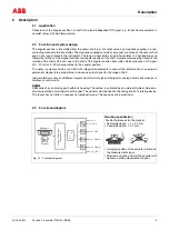
Fig. 2-1 Functional diagram
Mounting specification
Position tolerances for the magnet.
• Vertical deviation:
≤
1
±
0.1 mm
• Coaxial deviation:
≤
0.1 mm
• A sloping position of the actuator will impair
the measurement signal.
• After removing the actuator the encoder will
deliver an arbitry measurement signal.
Hall Sensor
Magnet
N
S
D
A
Sine-Cosine Signal
Inter
polator
+ V
s
±
10 V
0...10 V
4...20 mA
0...20 mA
- V (0 V)
s


