background image

37/62 

TLE Series 160 to 500 UL S2B

     UPS Installation Guide / REV-A


4.8.2


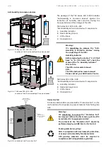
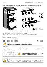
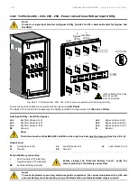
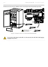
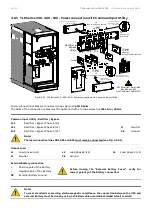
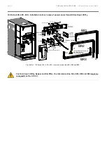
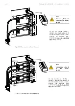
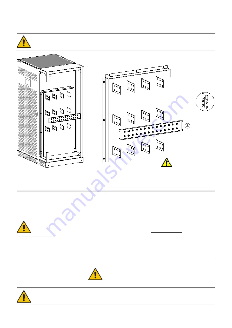
TLE Series 160 - 200 - 225 - 250 - Power connection with Dual Input Utility 


Note! 
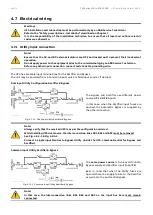
Connect a single input Neutral to Bypass Utility (inside the UPS, common Neutral for Bypass and 
Rectifier). 


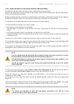
Fig. 4.8.2-1   TLE Series 160 - 200 - 225 - 250 - Power connection with Dual Input Utility 


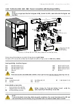
Power connection cables are connected to bus bars using 

M10 bolts

The bolts of the connection cables must be tightened with a torque wrench at 

355 Lb-in / 40 Nm


Dual Input Utility - Rectifier / Bypass 


L1-1 

Rectifier phase A (L1) 

L1-2


Bypass phase A (L1) 

L2-1 

Rectifier phase B (L2) 

L2-2


Bypass phase B (L2) 

L3-1 

Rectifier phase C (L3) 

L3-2


Bypass phase C (L3) 

PE


Ground 

N


Neutral 


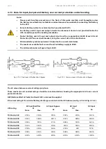
Note! 
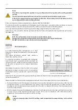
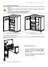
The interconnection links BR1, BR2 and BR3 on the input bus bars must be removed (see Fig. 4.8.2-3).


Output Load 


L1 

Load phase A (L1)


L2 

Load phase B (L2)


L3 

Load phase C (L3)


Neutral 

PE 

Ground 


External Battery connection 


Positive pole of the Battery 


Before closing the “External Battery Fuses”, verify for 

correct polarity of the Battery connection! 

Negative pole of the Battery 

PE 

External Battery Ground 


Note! 
To meet standards concerning electromagnetic compliance, the connection between the UPS and 
external Battery must be done by using a shielded cable or suitable shielded (steel) conduit! 


+

-

Typical installation

using common NEMA

 two hole lugs

PE

1

Rectifier

Utility

L1-1

N

Neutral Utility

Neutral Load

2

Bypass

Utility

L1-2

Load

L1

L2-1

L2-2

L2

L3-1

L3-2

L3

INTERCONNECTIONS LINKS

BR1, BR2 and BR3

MUST BE REMOVED

TLES_UL_1

60-250_S

2b_UPS co

nnection s

eparate_A

BB_01US

Summary of Contents for TLE Series

Page 1: ... UPS INSTALLATION GUIDE TLE Series 160 to 500 kVA UL S2B TLE Series 160 to 500 kVA UL S2B TLE Series 160 200 225 250 TLE Series 300 400 500 ...

Page 2: ...ion Concern Date Copyright 2020 by ABB Power Protection SA All rights reserved The information contained in this publication is intended solely for the purposes indicated The present publication and any other documentation supplied with the UPS system is not to be reproduced either in part or in its entirety without the prior written consent of ABB The illustrations and plans describing the equipm...

Page 3: ...he installation of the UPS Thank you for choosing ABB Start up and commissioning An ABB Global Services Field Engineer must perform start up and commissioning of the UPS Please contact ABB Service Center at least two weeks prior to schedule start up and commissioning at 1 800 292 3739 Distributed in the USA by ABB Service Center ABB Power Protection SA Via Luserte Sud 9 CH 6572 Quartino Switzerlan...

Page 4: ...0 is a Category C3 UPS Product according to IEC 62040 2 This is a product for commercial and industrial application in the second environment installation restrictions or additional measures may be needed to prevent disturbances We recommend that this manual be kept next to the UPS for future references If any problems are encountered with the procedures contained in this manual please contact you...

Page 5: ...ction with Common Input Utility 35 4 8 2 TLE Series 160 200 225 250 Power connection with Dual Input Utility 37 4 8 3 TLE Series 300 400 500 Power connection with Common Input Utility 40 4 8 4 TLE Series 300 400 500 Power connection with Dual Input Utility 42 4 8 5 Use of TLE Series 160 to 500 in eBoost Operation Mode 45 4 8 6 Use of TLE Series 160 to 500 as Frequency Converter 46 4 9 RPA Parallel...

Page 6: ... during Commissioning and Maintenance of the UPS for the following Damaged components squeezed wires and cables or not correctly inserted plugs After removing the sidewalls of the UPS make sure that all earth connections when reassembling are correctly reattached This UPS is intended for use in a controlled indoor environment free of conductive contaminants and protected against animals intrusion ...

Page 7: ...parate Battery terminals or to the cabinet or rack Do not lay tools or metal parts on top of the Battery and do not lay them where they could fall onto the Battery or into the cabinet 3 Disconnect charging source prior to connecting or disconnecting Battery terminals Install the Battery as shown on the drawing provided with the Battery When connecting cables never allow a cable to short across a B...

Page 8: ...gerous voltage present Risk of electric shock PE Earth GND Ground Protective Grounding terminal A terminal which must be connected to earth ground prior to making any other connection to the equipment A terminal to which or from which an alternating sine wave current or voltage may be applied or supplied A terminal to which or from which a direct current or voltage may be applied or supplied This ...

Page 9: ... 3 Control Panel Fig 2 1 4 Connectivity Rack Fig 2 1 2 TLE Series 160 200 225 250 General view with open doors Fig 2 1 5 Q1 UPS Output switch TLES_UL_160 250_S2b_UPS_ABB_02 SNMP CI J35µP XA 1 2 TLES_160 400_S2_Customer interface CI_SNMP_XA_01a E P O E P O Q1 I ON 0 OFF 1 2 E P O E P O TLES_UL_160 250_S2b_UPS_ABB_03 Q1 I ON 0 OFF TLES_UL_160 250_ S2b_Switch Q1_ABB_01 ...

Page 10: ...mer Interface Board see Fig 2 1 4 CR Connectivity Rack J35µP Serial port RS232 for IMV protocol Q1 UPS Output switch RPA RPA board Redundant Parallel Architecture for Parallel System option SNMP 3 ph SNMP WEB plug in adapter option see Fig 2 1 4 XA Terminals for EPO Emergency Power Off connection and 24Vdc for external Battery switch Remove this panel or provide means to capture metal filings from...

Page 11: ...ntrol panel Fig 2 2 4 Connectivity Rack Fig 2 2 2 TLE Series 300 400 500 General view with open doors Fig 2 2 5 Q1 UPS Output switch TLES_UL_300 500_S2b_UPS_ABB_02 SNMP CI J35µP XA 1 2 TLES_160 400_S2_Customer interface CI_SNMP_XA_01a E P O E P O Q1 1 2 I ON 0 OFF E PO E PO TLES_UL_300 500_S2b_UPS_ABB_03 Q1 I ON 0 OFF TLES_U L_300 500_S2b_Switch Q1_ABB _01 ...

Page 12: ... Interface Board see Fig 2 2 4 CR Connectivity Rack J35µP Serial port RS232 for IMV protocol Q1 UPS Output switch RPA RPA board Redundant Parallel Architecture for Parallel System option SNMP 3 ph SNMP WEB plug in adapter option see Fig 2 2 4 XA Terminals for EPO Emergency Power Off connection and 24Vdc for external Battery switch Remove this panel or provide means to capture metal filings from cu...

Page 13: ...ironmentally friendly material at the end of its service life must be recovered conforming to the local applicable regulations UPS packing materials must be recycled in compliance with all applicable regulations Recycling at the end of service life ABB in compliance with environment protection recommends to the User that the UPS equipment at the end of its service life must be recovered conforming...

Page 14: ... be lifted with a forklift in upright position Take note of the Center of Gravity marked on the package Warning Check for sufficient floor and elevator loading capacity Transport UPS only in upright position Do not stack other package on top of the UPS Crane Fig 4 1 2 Position of the carrying belts when moving the unpacked UPS Crane If the UPS has to be lifted by crane use suitable carrying belts ...

Page 15: ...345 lbs 610 kg Floor loading 129 lbs sq ft 630 kg m2 Fig 4 1 1 1 TLE Series 300 400 500 UPS cabinet dimensions TLE Series 300 400 500 Dimensions and weights Dimensions W x D x H 63 78 x 34 06 x 75 00 inches 1620 x 865 x 1905 mm Weight 2756 lbs 1280 kg Floor loading 187 lbs sq ft 914 kg m2 Note The weight of each single piece is marked outside the package 34 06 865mm 44 10 1120 mm 75 00 1905mm TLES...

Page 16: ...ot exceeding 13 F 25 C to 131 F 55 C In case the Battery is included please refer to Section 4 3 2 Some important functions of the UPS such as the customized functions are defined by parameters stored in a RAM memory A small backup Battery located on the Control Unit board supplies the RAM If the storage time of the UPS exceeds 1 year these functions should be verified by an authorized Service Cen...

Page 17: ...l consequences are explained in the User Manual to Section 9 1 4 read and understand them The TLE Series 160 to 500 UPS can radiate radio frequency energy Although some RFI filtering is inherent to the UPS there is no guarantee that the UPS will not influence sensitive devices such as cameras and monitors that are positioned close by If interference is expected the UPS should be moved away from th...

Page 18: ...of input and output cables Pay attention to the position of these openings when choosing the placement of the UPS These openings are covered with a protective plate Please remove the plate before drilling any holes 9 85 250 mm 44 10 1120 mm 0 99 25 mm 1 25 mm 29 53 750 mm 34 06 865 mm Utility input Output load Battery TLES_UL_160 250_S2b_UPS view top_ABB_01US Frontal side Utility input Output load...

Page 19: ...net on the floor Fig 4 4 1 7 TLE Series 160 200 225 250 UPS cabinet floor fixing points Fig 4 4 1 8 TLE Series 300 400 500 UPS cabinet floor fixing points TLES_U L_160 5 00_S2b_UPS fixing_A BB_01 2 13 54 mm 2 37 60 mm 44 10 1120 mm 27 56 700 mm 11 80 300mm Ø 0 5 3 1 3 5 m m 29 53 750 mm 34 06 865 mm 2 37 60 mm Frontal side TLES_UL_160 250_S2b_UPS view Bottom_ABB_02a 2 37 60 mm 29 53 750 mm 2 37 60...

Page 20: ...er exceed the range 4 F 20 C to 104 F 40 C The life of valve regulated Battery will be reduced by 50 for each additional 18 F 10 C that the Battery ambient temperature is above 77 F 25 C The Battery system associated with larger UPS is usually either rack mounted or installed in multiple Battery cabinets Installation and assembly must be made according to the local standards and Battery system man...

Page 21: ...the UPS system Contact your ABB Service Center for appropriate solutions The below table indicates the heat dissipation at full Load at PF 1 and charged Battery up to 3280 ft 1000 m altitude for cooling air 77 F 25 C to 86 F 30 C UPS model Losses Cooling air flow VFI eBoost option VFI PF 0 9 PF 1 PF 1 PF 0 9 PF 1 TLE Series 160 20137 BTU hr 5 9 kW 6826 BTU hr 1013 CFM 2 0 kW TLE Series 200 25256 B...

Page 22: ...vice Centre Fig 4 6 2 TiltWatch device Note Be aware of the heavy weight of the UPS pay attention when moving the UPS cabinet Take care not to damage the UPS when moving by forklift A damaged UPS must never be installed or connected to Utility or Battery In case of any damage sustained during the transport immediately inform the shipping agent A detailed report of the damage is necessary for any i...

Page 23: ...nents A Humidity indicator B Desiccant bag 5 pcs C VCI foil base D PE stretch foil Fig 4 6 5 Location of the Protective Foil Protective foil TLE Series 160 to 500 is provided with a Protective Foil on the roof and door front panels to prevent material from falling into UPS Warning It s mandatory to remove the Protective Foil but only just before the first start up of the UPS as indicated in the ap...

Page 24: ...ut sources if desired Dual Input Utility Configuration Rectifier Bypass Fig 4 7 1 1 Dual Input Utility Rectifier Bypass The Bypass and Rectifier use different power sources F1 and F2 inputs In this case when the Rectifier input fuses are opened the Automatic Bypass is supplied by the other connection Note Always verify that the received UPS is as per the configuration ordered While installing UPS ...

Page 25: ... the existence of voltage surge protection devices inside the UPS The connection of the Battery to the UPS must be protected with fuses or similar devices according to technical specifications and in accordance with local standards Note If you use ELCB breaker Earth Limiting Circuit Breaker to protect the input connections consider the high leakage current generated by the noise suppression capaci...

Page 26: ... maximum available fault current from the Battery supply is 20kA The minimum breaker voltage rating is 540V Fig 4 7 3 1 Dual Input Utility Rectifier Bypass Fig 4 7 3 2 Common Input Utility Rectifier Bypass The AC values below are current ratings per phase These maximum and nominal ratings should be considered when choosing the appropriate AC over current protection device NEC National Electric Cod...

Page 27: ...00 A 800 A TLE Series 400 700 A 600 A 600 A 500 A 700 A 600 A 1000 A 1000 A TLE Series 500 900 A 700 A 800 A 700 A 900 A 700 A 1200 A 1200 A Wiring Wire sizing according to NEC Section 210 20 a Table 310 16 Use 167 F 75 C copper or aluminum wire Wiring requirements AC Input Rectifier 3 Phase 4 wire plus Ground AC Input Bypass 3 Phase 4 wire plus Ground AC Output 3 Phase 4 wire plus Ground DC Input...

Page 28: ...5 75 3 85 100 110 65 75 85 2 95 115 130 75 90 100 1 110 130 150 85 100 115 1 0 125 150 170 100 120 135 2 0 145 175 195 115 135 150 3 0 165 200 225 130 155 175 4 0 195 230 260 150 180 205 250 215 255 290 170 205 230 300 240 285 320 190 230 255 350 260 310 350 210 250 280 400 280 335 380 225 270 305 500 320 380 430 260 310 350 600 355 420 475 285 340 385 700 385 460 520 310 375 420 750 400 475 535 3...

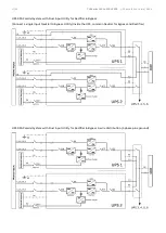
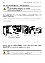
Page 29: ...nput Utility for Rectifier Bypass Single UPS with Common Input Utility for Rectifier Bypass 3 wire distribution 3 phase plus ground Single UPS with Dual Input Utility for Rectifier Bypass Connect a single input Neutral to Bypass Utility inside the UPS common Neutral for Bypass and Rectifier Single UPS with Dual Input Utility for Rectifier Bypass 3 wire distribution 3 phase plus ground ...

Page 30: ...60 to 500 UL S2B UPS Installation Guide REV A UPS RPA Parallel System with Common Input Utility Rectifier Bypass UPS RPA Parallel System with Common Input Utility Rectifier Bypass 3 wire distribution 3 phase plus ground ...

Page 31: ...Parallel System with Dual Input Utility for Rectifier Bypass Connect a single input Neutral to Bypass Utility inside the UPS common Neutral for Bypass and Rectifier UPS RPA Parallel System with Dual Input Utility for Rectifier Bypass 3 wire distribution 3 phase plus ground ...

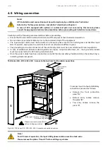
Page 32: ... connection of the electrical system must be in accordance with local regulations In case of additional cabinets containing Batteries input output transformers etc their ground terminals must be connected to the UPS main ground terminal Once the power cables have been connected re install the internal safety shields and close the cabinets by re installing all external panels TLE Series 160 200 225...

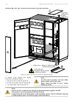
Page 33: ...e rotation must be clock wise Please remove the plates B and C before drilling any wholes Note Panel A B and C should never be removed or replaced with power applied to the UPS These panels are in close proximity to 480V live buss bars Always disconnect the Rectifier Bypass Load and Battery sources from the UPS before removing or replacing these panels If not serious injury or death could occur Q1...

Page 34: ...s input from thetop of the UPS PE L3 1 L2 1 L1 1 N Utility Neutral Load Neutral Load 1 Rectifier Bypass Utility BR2 BR3 BR1 PE PE Input Utility PE Load Use for top entry cables L3 L2 L1 PE PE Input Utility PE Load Attention Use only as additional PE TLES_UL_300 500_S2b_UPS connection_Top_ABB_01US Q1 Position of the cover protection for cables input from the bottom of the UPS Utility input Battery ...

Page 35: ... BR2 and BR3 must remain connected Output Load L1 Load phase A L1 L2 Load phase B L2 L3 Load phase C L3 N Neutral PE Ground External Battery connection Positive pole of the Battery Before closing the External Battery Fuses verify for correct polarity of the Battery connection Negative pole of the Battery PE External Battery Ground Note To meet standards concerning electromagnetic compliance the co...

Page 36: ...ther The output distribution cabinet must contain a Neutral Bus see Fig 4 8 1 2 If no Neutral Connection is available with the Bypass Input 3 wire input ground and the Load does not require a Neutral solidly connect the Output Neutral of the UPS to ground in the Output Distribution Cabinet Wire Neutral Conductors from the UPS to the output distribution cabinet common point of connection and solidl...

Page 37: ...ound N Neutral Note The interconnection links BR1 BR2 and BR3 on the input bus bars must be removed see Fig 4 8 2 3 Output Load L1 Load phase A L1 L2 Load phase B L2 L3 Load phase C L3 N Neutral PE Ground External Battery connection Positive pole of the Battery Before closing the External Battery Fuses verify for correct polarity of the Battery connection Negative pole of the Battery PE External B...

Page 38: ...ther The output distribution cabinet must contain a Neutral Bus see Fig 4 8 2 2 If no Neutral Connection is available with the Bypass Input 3 wire input ground and the Load does not require a Neutral solidly connect the Output Neutral of the UPS to ground in the Output Distribution Cabinet Wire Neutral Conductors from the UPS to the output distribution cabinet common point of connection and solidl...

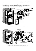
Page 39: ...60 200 225 250 Interconnection links BR1 BR2 and BR3 For Dual Input Utility Bypass and Rectifier the interconnection links BR1 BR2 and BR3 must be removed see Fig 4 8 2 3 Q1 Q1 I ON 0 OFF 1 2 36 BR1 3x20x1mm L 220mm 36 37 37 38 38 BR1 BR3 BR2 INTERCONNECTIONS LINKS BR1 BR2 and BR3 MUST BE REMOVED E PO E PO TLES_UL_160 250_S2b_UPS BR1 2 3_ABB_01US BR2 3x20x1mm L 220mm BR3 3x20x1mm L 220mm ...

Page 40: ...tery connection Positive pole of the Battery Before closing the External Battery Fuses verify for correct polarity of the Battery connection Negative pole of the Battery PE External Battery Ground Note To meet standards concerning electromagnetic compliance the connection between the UPS and external Battery must be done by using a shielded cable or suitable shielded steel conduit INTERCONNECTIONS...

Page 41: ...ther The output distribution cabinet must contain a Neutral Bus see Fig 4 8 3 2 If no Neutral Connection is available with the Bypass Input 3 wire input ground and the Load does not require a Neutral solidly connect the Output Neutral of the UPS to ground in the Output Distribution Cabinet Wire Neutral Conductors from the UPS to the output distribution cabinet common point of connection and solidl...

Page 42: ...hase A L1 L2 Load phase B L2 L3 Load phase C L3 N Neutral PE Ground External Battery connection Positive pole of the Battery Before closing the External Battery Fuses verify for correct polarity of the Battery connection Negative pole of the Battery PE External Battery Ground Note To meet standards concerning electromagnetic compliance the connection between the UPS and external Battery must be do...

Page 43: ...ther The output distribution cabinet must contain a Neutral Bus see Fig 4 8 4 2 If no Neutral Connection is available with the Bypass Input 3 wire input ground and the Load does not require a Neutral solidly connect the Output Neutral of the UPS to ground in the Output Distribution Cabinet Wire Neutral Conductors from the UPS to the output distribution cabinet common point of connection and solidl...

Page 44: ...nput Utility Bypass and Rectifier the interconnection links BR1 BR2 and BR3 must be removed see Fig 4 8 4 3 PE L3 1 L1 2 L2 2 with bottom cable entry PE L3 2 Load 2 Bypass Utility 1 Rectifier Utility PE PE with top cable entry L3 L2 L1 Q1 L2 1 L1 1 BR1 BR2 BR3 PE Attention Use only as additional PE 36 37 38 38 37 36 INTERCONNECTIONS LINKS BR1 BR2 and BR3 MUST BE REMOVED TLES_UL_300 500_S2b_UPS BR1...

Page 45: ...exhibits a predominantly capacitive characteristic it may provide some degree of reactive power compensation when combined with lagging power factor loads Conversely depending on the load type and level the UPS input characteristic may exhibit a leading power factor in eBoostTM Operation Mode Please contact your ABB Service Centre for more information Note If an emergency generator set supplies th...

Page 46: ... BR3 In order to avoid improper operation only the Rectifier input should be powered L1 1 L2 1 and L3 1 Fig 4 8 2 1 4 8 4 1 therefore the interconnection links BR1 BR2 and BR3 on the input bus bars must be removed See pictures above and Fig 4 8 6 1 and 4 8 6 2 Special care must be taken in choosing the fuse ratings installed in the output distribution max 20 of the UPS rated current Avoid high inr...

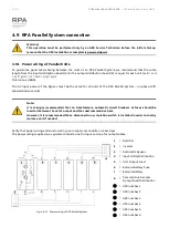
Page 47: ...RPA Parallel System no phase shift allowed between units Note It is strongly recommended that no transformers automatic circuit breakers or fuses should be inserted between the unit s output and the Load common bus bars However it is recommended that a disconnection or isolation switch is installed in order to totally isolate a unit if needed Verify that power wiring and control wiring run in sepa...

Page 48: ...tained between units in case one of the control cables should fail or be accidentally damaged or disconnected The standard length of the control bus cable between two parallel units is 40 ft 12m The maximal overall length of bus connection between the first and the last unit should not exceed 295 ft 90m Verify that control wiring run in an individual separate steel conduit Note Under no circumstan...

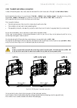
Page 49: ...1 1 2 3 4 5 6 must be in position ON see Fig 4 9 2 2 Fig 4 9 2 3 Bus connection on intermediate units Note Intermediate units of an RPA Parallel System On the two boards P13 P14 IM0222 Bus Interface Board of the intermediate units of a Parallel System the switches SW1 1 2 3 4 5 6 must be in position OFF see Fig 4 9 2 3 J2 J1 J2 J1 B A J1A 1 J1B 1 1 2 3 SW1 4 5 6 O N TLES_160 400_S2_RPA IM0222_02 J...

Page 50: ...ection The communication bus cable connectors are placed on the two boards P13 P14 IM0222 Bus Interface Board See Fig 4 9 3 1 and 4 9 3 2 Fig 4 9 3 3 View electronic module on intermediate unit Control bus cables connection Plug the cables J1A J2A 1 2 3 4 5 and J1B J2B 1 2 3 4 5 on the connectors J1A J2A and J1B J2B placed on the two boards P13 P14 IM0222 Bus Interface Board Fix the communication ...

Page 51: ...oard For reliability reasons the cables J1A J2A 1 2 3 4 5 and J1B J2B 1 2 3 4 5 connecting the units should be run in separated protected conduits as indicated in Fig 4 9 3 4 and 4 9 3 5 separated from the power cables It is important that the cable J1A J2A 1 2 3 4 5 must be the same length as cable J1B J2B 1 2 3 4 5 Warning Connection and commissioning of an additional UPS to an existing Parallel...

Page 52: ...s contact causes the immediate opening of the Contactors K6 and K7 as well as the shut down of Rectifier Inverter and Static Switch Note This procedure could imply a Load shut down Keep SELV cables separated from high voltage cables In a Parallel System a separate NC Normally Closed contact must be connected individually to each unit Fig 4 10 2 XA EPO Emergency Power Off RPA Parallel System connec...

Page 53: ...ed as follows Realize the push button EPO Emergency Power Off contact on XA EPO 1 EPO 2 is closed again Perform the Inverter OFF command from the screen Commands 1 Inverter OFF see User Manual to Section 6 5 In case of a Parallel System perform the Inverter OFF command from the screen Commands 1 Inverter OFF of each unit connected on the Parallel Bus and having its switch Q1 UPS Output closed CNT_...

Page 54: ...er boards for RPA Parallel System Note The installation of any option board must be performed only by an ABB Service Technician Prior to the installation connection and cabling of any option board the UPS must be completely powered down and all the power sources that will be connected to the option board must be de energized Option board shall be connected only to Safety Extra Low Voltage circuits...

Page 55: ...e User Manual Section 6 4 SETUP PRINTER Fig 5 1 2 Serial port J35µP connection to PC with RS232 1 1 cable DB9m DB9f The serial port J35µP RS232 is enabled on all the units of the RPA Parallel System Fig 5 1 3 Connector J1 RJ45 8P8C Note The serial port J35µP RS232 is enabled also in case the J1 RJ45 connector of the P4 Customer Interface see Section 5 2 1 is already connected J35µP RS232 TLE Serie...

Page 56: ...NC Normally Closed Output signals on voltage free contacts Programmable functions on input contacts On terminals X1 6 of the following 27 signals can be selected from the display entering with the appropriate Service Code Some UPS functions can be activated with parameters when an external Normally Open NO contact is closed on X1 10 21 or X1 11 22 Selectable functions by changing parameters Servic...

Page 57: ...RE def Parameter RL 1 X1 4 5 6 NO C NC LOAD ON INVERTER def Parameter RL 3 X1 7 8 9 NO C NC STOP OPERATION def Parameter RL 5 X1 12 13 14 NO C NC LOAD ON MAINS def Parameter RL 2 X1 15 16 17 NO C NC GENERAL ALARM def Parameter RL 4 X1 18 19 20 NO C NC BUZZER ACOUSTIC ALARM def Parameter RL 6 In case different alarms or operating status are required they can be configured on the same terminals via ...

Page 58: ...le to install the signal GENERATOR ON on X1 11 22 See Fig 5 2 1 X1 Since the Parameter for of the reading of the Generator function is Service Code protected call the nearest ABB Service Centre for it s activation When this contact closes it changes certain programmable functions such as Enabling or disabling of synchronization and consequently the Load transfer to generator Reduction or eliminati...

Page 59: ...contact of the External Maintenance Bypass Switch 5 2 7 X1 terminal block eBoost IEMi control signal The UPS operation in either eBoost or IEMi operating modes can be controlled via a NO Normally Open contact by installing the eBoost IEMi CONTROL signal routed to the programmable function contacts see Section 5 2 3 When this contact closes eBoost or IEMi operation mode is inhibited The Parameter f...

Page 60: ...ation Guide REV A 6 Notes 6 1 Notes Form It is recommended to note in this section Notes with date and short description all the operations performed on the UPS as maintenance components replacement abnormal situations etc Date Description Done by ...

Page 61: ......
Page 62: ...https library abb com ABB Power Protection SA Via Luserte Sud 9 6572 Quartino Switzerland abb com ups Copyright 2020 ABB All rights reserved Specifications subject to change without notice ...

Reviews: