B0431
Emax X1-Tmax T7-Tmax T8
13/66
Doc. No
Model
Apparatus
Scale
Page No
1SDH000587R0002
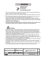
WARNING: In some installations, where particularly high harmonics occur, the current circulating on the neutral
may be higher than that of the phases.
WARNING: For three-pole circuit-breakers without external neutral, the Neutral protection setting must be Off,
otherwise the sensor presence error will be signalled (Error CS).
In these cases, connect T5-T6 to the sliding contacts, as shown in the wiring diagrams.
WARNING: Failure to comply with the setting limits of “I1” and “InN” may result in damage to the circuit-break-
er and consequent risks even for the operator.
WARNING: The protection setting is automatically 100% when the current value exceeds 15.5xIn on the neutral.
2.4.7. Protection against instantaneous short-circuit “Iinst”
The purpose of this protection is to maintain the integrity of the circuit-breaker and installation in the case of particularly high
current requiring shorter reaction times than those guaranteed by the instantaneous short-circuit protection.
The protection cannot be disabled. It has a single fixed time protection curve and the threshold level is exclusively at the charge
of ABB personnel.
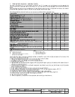
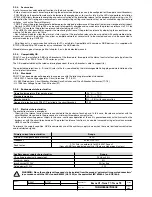
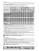
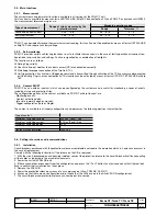
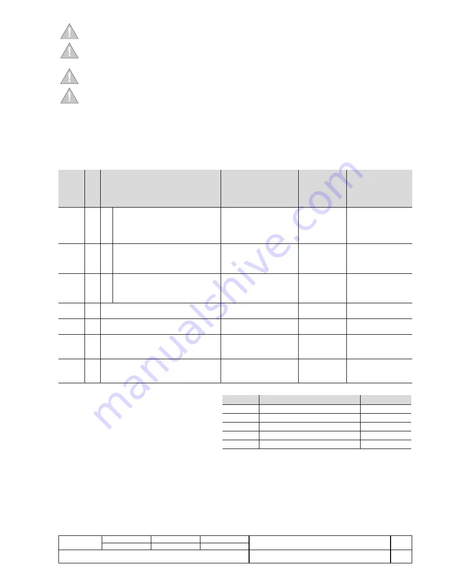
2.4.8. Summary table of protections
Pr
otection
Disabling
Trip threshold
Trip time
Trip
threshold
tolerance
(2)
Trip
time
tolerance
(2)
L
(t=k/I
2
)
I1
=
0.4 - 0.425 - 0.45 - 0.475 - 0.5 -
0.525 - 0.55 - 0.575 - 0.6 - 0.625 -
0.65 - 0.675 - 0,7 - 0.725 - 0.75 -
0.775 - 0.8 - 0.825 - 0.85 - 0.875 -
0.9 - 0.925 - 0.975 - 1 x In
t1
=
3 - 12 - 24 - 36 -
48 - 72 - 108 -
144 s
(1)
@I
f
=3I1
Release
between
1.05 and 1.2
x I1
± 10% I
f
≤
6 x In
± 20% I
f
> 6 x In
S
(t=k)
I2
=
1 - 1.5 - 2 - 2.5 - 3 - 3.5 - 4 - 5 -
6 - 7 - 8 - 8.5 - 9 - 9.5 - 10 x In
Where I
f
> I2
± 7% I
f
≤
6
x In
± 10% I
f
>6
x In
The best of the two data:
± 10% o ± 40 ms
t2
=
0.1 - 0.2 - 0.3 - 0.4 -
0.5 - 0.6 - 0.7 - 0.8 s
S
(t=k/I
2
)
I2
=
1 - 1.5 - 2 - 2.5 - 3 - 3.5 - 4 - 5 -
6 - 7 - 8 - 8.5 - 9 - 9.5 - 10 x In
t2
=
0.1 - 0.2 - 0.3 - 0.4 -
0.5 - 0.6 - 0.7 - 0.8 s
@ 10 In
± 7% I
f
≤
6
x In
± 10% I
f
>6
x In
± 15% I
f
≤
6 x In
± 20% I
f
> 6 x In
I
(t=k)
I3
=
1,5 - 2 - 3 - 4 - 5 - 6 - 7 - 8 - 9 -
10 - 11 - 12 - 13 - 14 - 15 x In
≤
30 ms
± 10%
MCR
(t=k)
6,0xIn
≤
I
5
≤
15xIn
step 0,1xIn
@I
f
>I
5
≤
30ms
(3)
±10%
G
(t=k)
I4
=
0,2 - 0,3 - 0,4 - 0,6 - 0,8 - 0,9 -
1 x In
Where I
f
> I4
± 7%
The best of the two data:
± 10% o ± 40 ms
t4
=
0.1 - 0.2 - 0.4 - 0.8 s
G
(t=k/I
2
)
I4
=
0,2 - 0,3 - 0,4 - 0,6 - 0,8 - 0,9 -
1 x In
Minimum trip time
± 7%
± 15%
t4
=
0.1 - 0.2 - 0.4 - 0.8 s
(1) The minimum value of this trip is 1s regardless of the type of curve
set (self-protection).
(2) These tolerances apply in the following conditions:
- Self-energized protection release in service conditions (no start-up)
with 2 or 3 supplied phases
and/or in presence of auxiliary supply. .
- operating temperature within the -25° ...70° range
- primary current values within the operating limits (see par. 1.2.7)
(3) The interval of time for which the protection is activated can be
selected via Ekip Connect, and is calculated from the moment the
CB closes.
For all cases not covered by the above hypotheses, the following tolerances apply:
Protection rip threshold
Trip time
L
Release between 1,05 e 1,25 x I1
± 20%
S
± 10%
± 20%
I
± 15%
≤
60ms
G
± 10%
± 20%
Others
± 20%
B1751


