B0431
Emax X1-Tmax T7-Tmax T8
16/66
Doc. no.
Model
Apparatus
Scale
Page No
1SDH000587R0002
2.5. Main functions
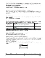
2.5.1. Measurement
The current measuring (ammeter) function is available in all versions of the PR331/P unit.
This function is accessible by means of test unit BT030-USB, Ekip T&P (connected to a PC) and PR010/T, or by means of HMI030.
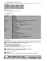
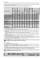
The measurement tolerance margins are:
Type of measurement
Range of values measured by the
protection release
Standard operation range
Range
Tolerance %
Phase and neutral current
0,05 ... 16 In
0,3 ... 6 In
± 1,5
Earth fault current
0,05 ... 4 In
0,3 ... 4 In
± 1,5
PR331/P can periodically record the maximum current reading: this function must be enabled by means of test unit BT030-USB
or Ekip T&P, and requires auxiliary voltage.
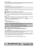
2.5.2. Self-monitoring
PR331/P provides certain self-testing functions so as to facilitate failure analysis in the case of faulty operation or incorrect con-
figuration of dip-switches and settings. Faults are signalled by a combination of led lights.
The functions are as follows:
Rating Plug validity.
Checks to find out whether the current sensors (CS) are connected correctly.
Watchdog for proper connection of the Trip Coil (TC ).
Hw Trip protection. If activated, a CB opening command is transmitted through activation of the TC if sensors are disconnected
or if the Rating Plug is not connected/faulty. This function can be activated by means of test unit PR010/T, BT030-USB or Ekip
T&P.
2.5.3. Contact S51/P1
PR331/P has an external contact, which can be configured by the customer and is useful for monitoring a series of events,
including alarms and protection trips.
The configuration options of the contact, available via PR010/T or Ekip Connect, are:
- Monitoring event/s;
- Contact activation delay;
- Idle state (normally open or closed);
- Trigger configuration (Auto or Single).
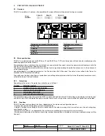
The contact is available in all supply configurations and possesses the following electrical characteristics:
Type of contact
Maximum switching voltage
400 Vac (Peak) / Vdc
Maximum switching current
0.1 Aac (Peak) / Adc
Maximum switching power
40 W
Contact/Circuit insulation
1500 Vac
2.6. Putting into service and recommendations
2.6.1. Installation
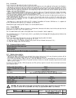
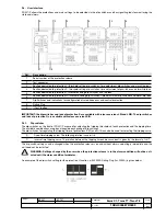
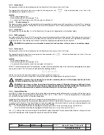
Circuit-breakers purchased with the protection release assembled do not require this operation which is, however, necessary in
the case of replacement.
Comply with the following instructions if the release on the CB is replaced:
1. With the circuit-breaker open and possibly isolated, connect the protection release to the circuit-breaker itself by connecting
all the cables as indicated in the assembly documents.
2. Power the unit with PR030/B only.
3. If there are no other errors apart from the configuration one, press the “i Test” button for a few seconds until all the red leds
flash to confirm that installation has taken place.
4. Remove the PR030/B.
5. Power the protection release by means of any supply source (Vaux, PR030/B, PR010/T).
6. Make sure that there are no configuration errors (check that the LEDs are on in the Alive LED ON configuration).
7. The circuit-breaker and protection release can now be put into service.
B1751

