B0431
Emax X1-Tmax T7-Tmax T8
59/66
Doc N°
Mod.
Apparatus
Scale
Page No
1SDH000587R0002
3.12. Putting into service and recommendations
3.12.1. Installation
Circuit-breakers purchased with the protection release assembled do not require this operation which is, however, necessary in
the case of replacement.
Comply with the following instructions if the release on the CB is replaced:
1. With the circuit-breaker open and possibly isolated, install the protection release on the circuit-breaker
2. Power the protection release with PR030/B only
3. If there are no other errors, the display will show the message Configuration (configuration error) accompanied by the yellow
LED coming on permanently (warning)
4. Enter the unit’s “Settings” menu
5. Select “Circuit-breaker”
6. Select “Unit installation”
7. Input the password
8. Select “Install” and press “ENTER”
9. When the red led flashes on and off and the message Installation (installation error) is displayed, remove the PR030/B
10. Energize the protection release from any other source
11. Check for the absence of configuration errors.
3.12.2. Uninstalling
To complete the procedure for uninstalling a PR332/P or PR333/P unit, follow the steps below:
1. With the circuit-breaker open and/or isolated, power the protection release with PR030/B
2. Enter the unit’s “Settings” menu
3. Select “Circuit-breaker”
4. Select “Unit installation”
5. Input the password
6. Select “Uninstall” and press “ENTER”
7. Remove the PR030/B
8. Remove the PR332/P or PR333/P unit from the circuit-breaker
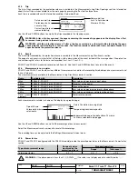
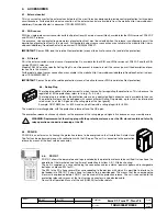
9. The remove the TC connector, proceed as indicated in the figure alongside.
The uninstalling
procedure is not strictly necessary for operation but is strongly recommended as it
allows allows circuit-breaker parameters such as contact wear and others that would otherwise be lost,
to be stored. The data in question are then re-transmitted to the new protection release to be installed in the same circuit-breaker.
3.12.3. Connections
WARNING: For the connections provided by the user, it is recommended that you comply strictly with the rec-
ommendations contained in this document. This will ensure compliance with all the international reference
standards and guarantee that the protection release functions perfectly even in heavy duty environmental and
electromagnetic conditions.
Pay particular attention to the types of cable, the connections to earth and the maximum distances.
3.12.4. CS and TC connection test
WARNING: If PR332/P has been installed by the user, it is important, before closing the CB, to check the last
line on the display when the protection release is turned on for the first time via a PR030/B battery module. No
CS and/or TC disconnected messages must appear; if they do, do not close the circuit-breaker and make the
correct connections.
3.12.5. Current sensor connection for external neutral
WARNING: If you want to connect the current sensor for the external neutral conductor to a three-pole circuit-
breaker, remember to set I
n
N. accordingly. During this procedure, the circuit-breaker must be open and prefer-
ably isolated.
3.12.6. TV connections
All the application and functional details for correct use of the TV are described in par. 1.10.1.3.
3.12.7. How to put the Rc sensor into service
If PR332/P and PR333/P are to be provided with the Rc function, comply with the instructions below:
1. Disconnect all power supplies;
2. Comply with the instructions in document 1SDH000616R0001: install the supplied rating plug and XK2 cable for the RC ap-
plication.
3. Install the toroid on the busbars as shown in the 1SDH000601R0001 document;
4. Connect the toroid to the protection release as shown in the circuit diagram
5. Energize the protection release via PR030/B, then proceed with the installation operations in the following sequence: settings,
CB, earth protection, external toroid, RC. Confirm the changes;
6. Check that no failures are indicated;
7. Set threshold and times of Rc protection;
8. Conduct an Rc test (see par. 1.11 Menù Test); check for correct operation.
B1751

