B0431
Emax X1-Tmax T7-Tmax T8
61/66
Doc N°
Mod.
Apparatus
Scale
Page No
1SDH000587R0002
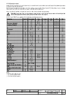
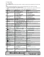
3.14. Troubleshooting
3.14.1. Troubleshooting
The following table lists a series of typical service conditions, to help you understand and solve hypothetical faults or malfunctions.
Note:
1. Before consulting the following table, check for any error messages appearing for some seconds on the display.
2. FN indicates that the protection release is operating normally.
3. In the case where the suggestions proposed do not lead to a solution of the problem, please contact the ABB assistance
service.
4. If possible, use the external communication units and supply a report downloaded by means of Ekip Connect.
N° Situation
Possible causes
Suggestions
1
The trip test cannot be run
1. The busbar current is > 0
2. The TC is not connected
1. FN
2. Check the messages on the display
2
Trip times lower than ex-
pected
1. Threshold too low
2. Curve too low
3. Thermal memory enabled
4. Incorrect Neutral Selection
5. The SdZ is inserted
1. Correct threshold
2. Correct curve
3. Exclude if not necessary
4. Correct Neutral Selection
5. Exclude if not necessary
3
Trip times higher than
expected
1. Threshold too high
2. Curve too high
3. Curve I
2
t inserted
4. Incorrect Neutral Selection
1. Correct threshold
2. Correct curve
3. Exclude if not necessary
4. Correct Neutral Selection
4
Rapid trip, with I3=Off
Iinst tripped
FN with short-circuit with high I
5
High earth I, but no trip
happens
1. Incorrect selection of the sensor
2. Function G prevented with I>4In
1. Set int. or ext. sensor
2. FN
6
Display off
1. Vaux missing and the current and/or
voltage are below the minimum value.
2. Temperature off range
1. FN, see par. 1.4.3
2. FN, see par. 1.3.7 and see par. 1.6.17
7
The display is not back-lit
Current and/or voltages below the limit for
lighting the display
FN
8
Reading of I incorrect
Current below the minimum threshold that
can be displayed
FN
9
Reading of V, W and power
factor incorrect
1. Connection error between VT and
PR330/V
2. Voltage parameter configuration error
1. Check connections between VT and PR330/V
2. Set correct parameters
10
“
Local Bus” message
on display
No communication between PR333/P
and Flex
Interface or HMI030
1. If not present, disable PR021/K, see par. 1.9.3
2. Check bus connection
3. Check external device
11
Message “” instead of
expected data
Function disabled or data off range
FN
12
The expected trip does not
occur
Trip function disabled
FN enable trip if necessary
13
No activation of the Unbal-
ance U protection
Values of I out of range
FN, see par. 1.6.11
14
No display of the opening
data
Vaux missing,the buffer capacitor is dis-
charged
FN, see par. 1.7.2
15
The password is not re-
quested
The password has been disabled
FN, re-enter the password with a value other
than 0000
16
Impossible to change any
parameter
PR333/P in alarm situation
FN
17
“
Temp. sensor” or
“
Start-up” message
Possible fault inside the protection release Contact ABB
18
Invalid date
1. First installation
2. Information lost due to power failure
Change date, see par. 1.9.8
19
Untimely trip
See par. 1.4.3.2
20
LED lighting
See par. 1.4.1
21
The language cannot be
changed
1. The protection release is configured in
the remote mode
2. CB not open
3. Vaux or PR330/V or PR030/B not in-
stalled
1. Set locally
2. Open CB
3. Power the protection release
22
The activation contact
of protection MM is not
closed
Protection MM has not been enabled or
K14/15 has no incoming signal
Check the menu to make sure that the protec-
tion is enabled and use a tester to check that
voltage and polarity at the ends of K14 and K15
are correct
B1751

