16
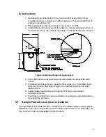
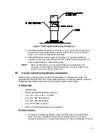
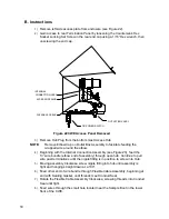
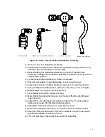
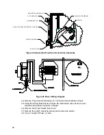
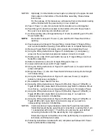
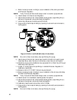
Figure 20 Sample Conditioning Module Installation
6)
If necessary, install reducer into Sample Probe output fitting.
7)
Install ferrule and Nut onto one end of the sample tubing.
8)
Insert tubing with ferrule into Reducer/Sample Probe output fitting. Move Nut
down onto ferrule, screw onto fitting and tighten.
9)
Install ferrule and Nut onto other end of the sample tubing.
10)
Insert ferrule into Sample Conditioning Module input fitting. Move Nut down
onto ferrule, screw onto fitting and tighten.
11)
Locate sample output fitting on Sample Conditioning Module.
12)
Locate sample input on NGC Feed-Through Assembly and remove sealing
Screw.
NOTE:
Make necessary bends in tubing to ease installation of the tubing into
output fitting on Sample Conditioning Module, and ferrule and valco Nut
into input on NGC Feed-Through Assembly.
13)
Insert tubing with ferrule into output fitting on Sample Conditioning Module.
Move Nut down onto ferrule, screw onto fitting and tighten.
14)
Remove plastic caps from Restrictor Coils, sealing screws from Feed-
Through Column Vents and sealing screw from Sample Vent lines.
15)
Purge air from the transport tubing by opening the shut-off valve located on
the Sample Probe.
NOTE:
Be sure to follow local codes when performing this purge.
16)
Insert tubing with ferrule into corresponding input port located on the NGC
Feed-Through Assembly. Move valco Nut down onto ferrule, screw into port
and tighten.
17)
Repeat for each additional Sample Stream.
18)
Measure and cut Vent Tubing to sufficient length to guarantee Purge Coils
vent outside of CWE. Feed Vent Tubing through Sample Boot.

