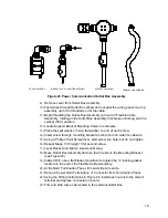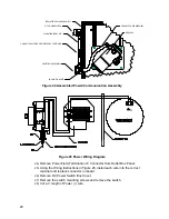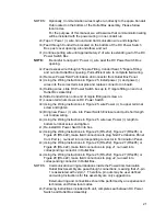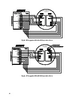
17
19)
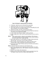
Make necessary bends in tubing to ease installation of tubing into the
required fittings on the end of Sample Conditioning Module Purge Coil.
20)
When all connections are complete, apply aerosol insulating foam from inside
the enclosure pointing toward the outside of boot, ensuring that the overspray
falls outside the enclosure.
NOTE:
DO NOT over tighten. After securing tubing, check for gas leaks.
21)
Please follow Heat Trace Manufacturer’s suggested installation instructions
for applying Heat Trace equipment to additional Sample Streams.
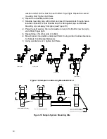
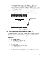
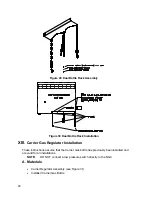
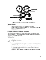
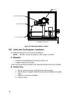
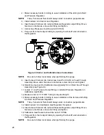
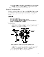
Figure 21 Sample Boot
XI.
CWE Optional Pwr/Comm Outlet Box Assembly
If installing the NGC inside a Cold Weather Enclosure, use this procedure to install the
optional RS-232/RS-485/RS-422 Outlet Box (P/N 2102296-xxx) if required, otherwise
continue to the next applicable instructions. Before you begin, review the procedure and
the materials required for installation.
A. Materials
•
1 ea. Outlet Box Assembly
•
1 ea. Internal NGC Connection Assembly
•
1 ea. Flexible Cable Assembly
•
1 ea. DC Power Switch Box
•
1 ea. Support Bracket
•
2 ea. 10-32 x ¾” SS Pan Head Screw, Phillips
•
2 ea. #10 SST Flat Washer
•
2 ea. #20 SST Split Washer
•
Materials for external wiring (to Outlet Box) not provided by Totalflow. Quantities
and materials to be determined by the technician based on installation and local
codes.

