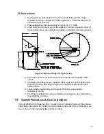
4
III.
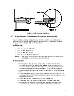
Freestanding Cold Weather Enclosure Installation
The following steps will typically require two people.
A. Materials
•
4 ea. ½-13 x 1 ¼ SST Bolt
•
4 ea. ½ SST Flat Washer
•
4 ea. ½” SST Split Washer
•
1 ea. Stand
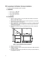
B. Installation
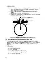
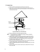
1)
Stand is made symmetrical, so top and bottom are identical. Locate stand
base on a flat, stable, surface.
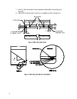
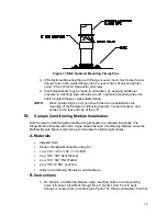
2)
Set enclosure on top of stand, oriented so that the stand brace is horizontal
with front of enclosure (see Figure 4).
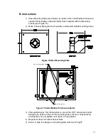
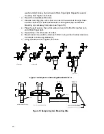
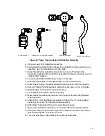
3)
Place a split washer , then a flat washer on one of the 1 ¼” Bolts and insert
through bolt hole located in the angle iron into the outermost corner of the
enclosure (see Figure 5).
4)
Move channel Nut into position so that Bolt will screw into Nut. Screw Bolt
into Nut.
Figure 4 Typical CWE Stand Mount Installation
5)
Repeat for all other corners.
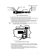
6)
Position enclosure on stand, centering stand underneath or offset as desired
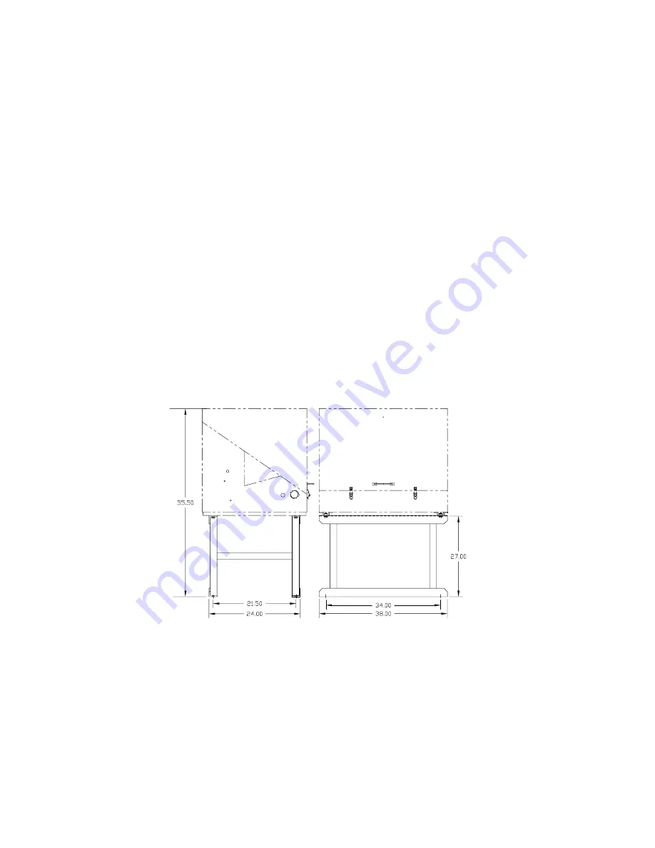
and tighten all Bolts.
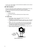
7)
Foot Plate mounting holes are pre-drilled for mounting to a pad. Hardware to
be supplied by customer.