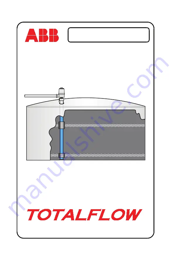
background image


MEASUREMENT & CONTROL SYSTEMS

LevelMaster Start-Up Guide


Summary of Contents for TOTALFLOW LevelMaster Series

Page 1: ...MEASUREMENT CONTROL SYSTEMS LevelMaster Start Up Guide ...

Page 2: ...owing information is intended as a quick start reference guide for the installation setup and configuration of the Totalflow LevelMaster level sensor For more comprehensive information regarding the LevelMaster refer to the LevelMaster User s Manual Totalflow recommends that the user first read this documentation before beginning installation to become familiar with the steps necessary to complete...

Page 3: ...the LevelMaster Two floats The float labeled OIL is put on first with the arrow pointing towards the top of the LevelMaster The next float labeled WATER is put on next with its arrow also pointing towards the top of the LevelMaster Figure 2 LevelMaster Assembly 5 Slide a float clamp over the bottom of the LevelMaster casing and lock clamp in place with a screw driver or nut driver Ensure the clamp...

Page 4: ...matics for three different types of hosts XSeries Flow Computer XFC XSeries Remote Controller XRC and LevelMaster Controller LMC It is possible to connect directly to the LevelMaster utilizing only a laptop that is running MasterLink software wherein the user plugs the computer directly into the LevelMaster s electronic board using a converter cable P N 2100241 xxx The LevelMaster also has the abi...

Page 5: ...g The Totalflow XSeries flow computer supports the LevelMaster while performing their duties as a flow computer All XFC models are wired identically See Figure 4 for wiring instructions Figure 4 XFC Wiring Interconnect ...

Page 6: ...J17 21 J16 CHARGER INPUT BATT XRC Board 2100355 J4 J3 J1 CHANNEL 1 CHANNEL 2 CHANNEL 3 CHANNEL 4 GND 1 POWER OUT 2 Channel 1 Channel 2 Channel 3 Channel 4 J2 1 JP1 J1 T T R R V V POWER 1 POWER 2 POWER 3 1 3 BUS BUS VBATT GND BUS BUS GND VBATT J23 From XRC Board To Barrier Board To Barrier Board To LevelMaster Board J6 10 VBATT J1 1 J2 2 J1 V J6 11 GND J1 3 J2 1 J1 V J6 15 BUS J4 1 J3 1 J1 T J6 17 ...

Page 7: ...erconnect 1 XA1 1 J17 21 J6 J16 CHARGER INPUT COMM 1 BATT 10 LMC7100 Board 2101210 J4 J3 J1 CHANNEL 1 CHANNEL 2 CHANNEL 3 CHANNEL 4 GND 1 POWER OUT 2 Channel 1 Channel 2 Channel 3 Channel 4 J2 1 JP1 J1 T T R R V V POWER 1 POWER 2 POWER 3 1 3 BUS BUS VBATT GND BUS BUS GND VBATT From LMC Board To Barrier Board To Barrier Board To LevelMaster Board J6 10 VBATT J1 1 J2 2 J1 V J6 11 GND J1 3 J2 1 J1 V ...

Page 8: ...termediate jumpers 3 and 5 are used per their factory setting Note The MasterLink cable will not operate with the 4th jumper installed Remove this jumper if connecting directly to the electronics board then replace jumper 4 Last Board or Only Board Pin 13 only Pin 11 only Pin 9 10 jumper Pin 7 8 jumper Pin 5 6 jumper Pin 3 only Pin 1 Only First or Intermediate Board Pin 13 only Pin 11 only Pin 9 1...

Page 9: ...the LevelMaster are installed and power is applied to unit Additionally the LevelMaster is RS 485 only and will need to be converted to RS 232 to communicate with the laptop computer 1 Connect the converter cable between the communication ports on the laptop computer and the LevelMaster communication connector see Figure 8 Level Master Board P N 2018546 xxx Cable Assembly P N 2100250 xxx Cable Ass...

Page 10: ...crement each ID number by 1 i e first LevelMaster 1 second LevelMaster 2 etc Click the Setup LevelMaster button 5 A dialog box displays asking if the user wants to add the LevelMaster to their list Click the Yes button 6 A similar dialog box then displays asking to name the corresponding LevelMaster Assign a name to the device and click the OK button 7 Verify that the LevelMaster was successfully ...

Page 11: ...l level value in the Tank Level 1 field and clicking the Set Tank Level button Note Calibrating the levels sets a bias for all levels 10 Next click the Upload Download tab see Figure 11 After navigating to the respective area where the user wants to save their setup configuration click the Read and Save Data to File button This enables the user to save the settings so that they can be uploaded aga...

Page 12: ...g procedure assumes that there are no other LevelMaster applications already installed 1 After connecting the computer to the local communications port on the side of the XFC or XRC enclosure open the PCCU32 software 2 Logon to PCCU32 as an administrator 3 Click the Entry icon to move to the Entry screen 4 In the tree view click on the Station ID and move to the Applications tab see Figure 12 Figu...

Page 13: ...d expand the LevelMaster application by clicking next to LevelMaster The number of tanks set in the Value field from the previous step are reflected as individual numbered entries 10 In the tree view expand the Communications entry by clicking next to Communications 11 Select the LevelMaster port and click on it to open the Setup window 12 Within the Setup window set the values for the Protocol Le...

Page 14: ...e then File Utilities and then LevelMaster Request Block Editor from the drop down menu 15 In the LevelMaster Request Block Editor window enter in the Application number 20 the Tank Number number of Sensors unit ID and the time Interval see Figure 16 Figure 16 LevelMaster Request Block ...

Page 15: ... there is no capability for developing a strapping table Since this is the case the user may enter a new figure for each level thus allowing the user to adjust for the density of the liquid that affects the float level When using host software PCCU32 WinCCU Remote Host Console or Modbus the host software can be used to configure strapping tables and view calculated gross values Table Factors The f...

Page 16: ...outside influence namely a damaged section of the tank a strapping table allows for a more accurate adjustment This allows the user to make a correction based only on the area damaged rather than an adjustment to the entire volume of the tank by setting a bias level The calibration can be performed by either MasterLink or PCCU software MasterLink When communicating directly with the LevelMaster fr...

Page 17: ...l offset calculation error Compensated value below 0 or above 655 Temperature 0010 No ICOMP signal Detection of broken primary coil The box needs to be tested 0020 Broken secondary wire The box needs to be tested 0030 Analog to digital converter saturation See below Float 1 Bottom Float 1000 No ICOMP signal Detection of broken primary coil The box needs to be tested If OPEN the sensor needs to be ...

Page 18: ... to be changed click the drop down arrow and select the desired setting Upon selection click Send New Value Testing the Sensor The following information will take the user through the process of testing the LevelMaster sensor 1 Remove the Killark conduit dome cover on the top of the LevelMaster sensor and disconnect the green phoenix connector 2 Remove the yellow fiberglass tension support and the...

Page 19: ...ble on the backside of the test box the sensor passes the test If the test fails the reading will normally be open or shorted wires If this is the case the sensor will need to be replaced 8 Disconnect the ribbon cable from the test box cable and reconnect the ribbon cable to the interface board 9 Set the board in the conduit housing and replace the yellow fiberglass tension support 10 Reconnect th...

Page 20: ...ABB Inc Totalflow Products 7051 Industrial Blvd Bartlesville Oklahoma 74006 Tel USA 800 442 3097 International 001 918 338 4880 ...

Reviews: