background image

Operation Manual / TPR56-F + TPR61-F

2  Safety / 2.1  Introduction

© Copyright 2018 . All rights reserved.

HZTL2490_EN

Revision D

May 2018

2 Safety

2.1 Introduction

Turbochargers manufactured by ABB are state of the art and comply
with the pertinent safety and health-protection requirements that ap-
plied when the turbocharger was manufactured. Consequently, the tur-
bocharger is safe to operate. Nevertheless, during turbocharger opera-
tion and when working on the turbocharger, residual risks can exist
which:

¡

originate from the turbocharger itself and its accessories

¡

originate from the operating and auxiliary materials used

¡

are the consequence of insufficient observance of the safety instruc-
tions

¡

are the consequence of unsatisfactory and improper execution of
maintenance and inspection work.

The operating company is responsible for access to the turbocharger as
well as the organisational measures that regulate the safe handling of
the turbocharger by its personnel.

All instructions contained in this chapter must be observed for safe and
trouble-free operation of the turbocharger and during all work on the
turbocharger.

All further safety instructions contained and specifically identified in
every chapter of this manual (see section Definition of Safety Instruc-
tions) must also be observed.

2.2 CE conformity

Information

ABB turbochargers fulfil Directive 2006/42/EC on machinery and are
considered partly completed machinery in the sense of Article 2 g.

Page 

14

 / 

79

Summary of Contents for TPR56-F32

Page 1: ... Systems Ltd CH 5401 Baden Type TPR56 F32 HT554216 nMmax 724 t Mmax 680 nBmax 686 t Bmax 650 1 s C 00360 36 50 50 Year 2019 made in Switzerland Application according to the Operation Manual kg HZTL2490 English TPR56 F32 Original Operation Manual ...

Page 2: ...Replacement intervals of components depends on the load profile turbine inlet temperature suction air temperature and turbocharger speed In case the operation conditions differs significantly from what is considered to be normal for the cur rent application it is recommended to contact ABB for a re calculation of replacement intervals Frequent load alterations high temperatures and high speed lowe...

Page 3: ...gns 15 2 4 Definition of Safety instructions 15 2 5 Warning plates on the turbocharger 16 2 6 Safe operation and maintenance 17 2 7 Hazards during operation and maintenance 20 2 8 Periodic checking of the pressure vessel 25 2 9 Lifting loads 26 3 Start up commissioning 27 3 1 Oil supply 27 3 2 Inspection work 30 3 3 Commissioning after taking out of operation 32 4 Operation 33 4 1 Noise emissions ...

Page 4: ...ion 55 8 2 Module weights 57 8 3 Removing and installing the air suction branch filter silencer 58 8 4 Axial clearance 60 8 5 Removing cartridge group 61 8 6 Dismantling and installing the turbine diffuser and nozzle ring 65 8 7 Installing cartridge group 67 8 8 Table of tightening torques 70 9 Mothballing the turbocharger 72 9 1 Taking the engine out of operation for up to 12 months 72 9 2 Taking...

Page 5: ...rbocharger and contains instruc tions for safe operation The Operation Manual is a complement to and expansion of existing na tional regulations for occupational safety accident prevention and envir onmental protection Target group The Operation Manual is aimed at engineers and trained mechanics re sponsible for the proper operation of the engine and for the turbochar ger connected to it Availabil...

Page 6: ...right 2018 All rights reserved HZTL2490_EN Revision D May 2018 1 2 Layout and function 01 Suction branch filter silencer 06 Gas inlet casing 02 Compressor wheel 07 Nozzle ring 03 Diffuser 08 Turbine 04 Bearing bush 09 Bearing casing 05 Gas outlet casing 10 Compressor casing Page 4 79 ...

Page 7: ...xhaust gases then escape into the open air through the gas outlet casing 05 and the exhaust gas pipe connected to it The rotor runs in two radial plain bearings which are located between the compressor and the turbine in the bearing bush 04 The axial bear ing is also a plain bearing The plain bearings are connected to a central lubricating oil duct which is normally supplied by the lubricating oil...

Page 8: ...ate of the art This turbocharger was built according to state of the art technology and is operationally safe according to recognised safety regulations WARNING Improper operation and maintenance of the turbocharger can result in danger to life and limb of the user or third parties In addition im proper use may cause damage to the machine u The machine may be operated only by trained personnel Use...

Page 9: ...n the sense of the Hazardous Sub stances Ordinance Nevertheless the following points are to be ob served when handling VCIs u Observe specifications in the safety data sheet u Ensure good room ventilation u Do not eat drink or keep food at the workplace while working with VCIs u Clean hands and face after working with VCIs u For further information refer to www branopac com Wear safety gloves to p...

Page 10: ...e group must be inspected by an ABB Turbocharging Service Station and repacked u Inspect the package for damage If the package is damaged the tur bocharger or cartridge group must be inspected by an ABB Tur bocharging Service Station and repacked After every 3 years the following work steps must be performed by an ABB Turbocharging Service Station Inspect the components Replace the desiccant agent...

Page 11: ...and wearing of personal protective equipment NOTICE The manner in which personnel work on and with the turbocharger with regard to safety and risks is to be checked on a regular basis in accord ance with the Operation Manual u The turbocharger must be shut down immediately in the event of modifications affecting safety or of corresponding operating beha viour by stopping the engine The fault shoul...

Page 12: ...nce of personnel The turbocharger must only be operated and serviced by trained and au thorised personnel Basic mechanical training is a prerequisite Design variants This document is valid for different design variants of turbochargers There may be sections and descriptions of components that are not rel evant for a specific turbocharger variant ABB Turbocharging Service Stations will be happy to ...

Page 13: ...ct Definition of mandatory signs Mandatory signs show the protective equipment to be worn for a task The mandatory signs are described in chapter Safety and must be com plied with Definition of caution warning The caution and warning signs are described in the chapter Safety ABB Turbo Systems In this document ABB Turbo Systems Ltd is abbreviated to ABB Turbo Systems Official ABB Turbo Systems Serv...

Page 14: ...agreed with the enginebuilder 02 Turbocharger operating limits during operation Recommended replace ment intervals for tur bocharger components 03 Replacement interval for plain bearings in 1000 h 04 Replacement interval for compressor in 1000 h 05 Replacement interval for turbine in 1000 h Further information 06 Part number for customer 07 Designation of special design 08 Turbocharger weight in k...

Page 15: ...tMmax normally apply only when running at overload 110 during trials on the engine test bed Operation above nMmax and tMmax is not permit ted Non observance of the recommended replacement intervals increases the risk of unpredictable component failures 1 7 2 Positions of the rating plates A rating plate is attached to the turbocharger foot one on the left and one on the right On turbochargers with...

Page 16: ...ce of insufficient observance of the safety instruc tions are the consequence of unsatisfactory and improper execution of maintenance and inspection work The operating company is responsible for access to the turbocharger as well as the organisational measures that regulate the safe handling of the turbocharger by its personnel All instructions contained in this chapter must be observed for safe a...

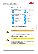
Page 17: ...r protection 2 4 Definition of Safety instructions The following symbols and terms used in this manual concern safety or refer to possible hazards WARNING Definition of warning Serious personal injuries and even accidents with fatal consequences may occur if work and operating instructions marked with this symbol and the word WARNING are either not followed or not followed pre cisely u Warning sig...

Page 18: ...ng plates that must be observed are attached to the turbocharger The warning plates must always be present in the intended locations and must be legible Part number Size mm Product 81080 105 x 74 TPR When uninsulated turbochargers are delivered to the engine builder the warning plates must be subsequently attached to the insulation This is the responsibility of the engine builder Page 16 79 ...

Page 19: ...n the turbocharger if you are under physical or mental stress u Work only with suitable tools as well as equipment and working ma terials that are in perfect condition u Electric tools must be solidly earthed and connecting cables may not be damaged u Keep the workplace clean clear away loose objects and remove obstacles on the floor u Keep the floor equipment and the turbocharger clean u Have oil...

Page 20: ...age or changes in operational perform ance to person responsible u If damage is discovered immediately shut down turbocharger and se cure it against inadvertent or unauthorized use u When switching on auxiliary power sources hydraulics pneumatics electricity water keep an eye open for any hazards resulting from supplying these power sources Safety during cleaning If cleaning agents or solvents are...

Page 21: ... the supply of oil is interrupted especially with an external oil supply u Put the engine into operation only after all parts have been refitted properly CAUTION Mechanical work on the turbocharger Possible damage to or destruction of components on the turbocharger u Perform only those tasks that are described in this manual u Perform work only for which training has been carried out Safety when t...

Page 22: ...ocharger in accordance with instructions u During maintenance work secure the rotor against unintentional ro tation Mechanical hazards when working on the turbocharger During maintenance work various risks can occur through the improper handling of components through the non observance of work instruc tions due to inadequate care or as a consequence of insufficient train ing WARNING Mechanical haz...

Page 23: ... 85 dB A always wear ear protection Wear ear protection Hazards due to hot surfaces and substances During operation turbocharger surfaces and attached parts as well as operating materials lubricating oil become hot The surface temperat ure is dependent on the effectiveness of the insulation being used The temperature can become high enough so that it falls into ranges where burns are possible WARN...

Page 24: ...arger surfaces is compuls ory Wear safety gloves to protect against thermal hazards Hazards due to operating and auxiliary materials Operating and auxiliary materials are substances used for operation or the execution of maintenance work Oils greases coolants cleaning agents and solvents acids etc can be regarded as hazardous materials Operating and auxiliary materials can be combustible and easil...

Page 25: ...tamination of the ground and water due to improper disposal can lead to environmental damage u Handle operating and auxiliary materials carefully u Heed the instructions for use safety data sheets and hazard notices on the containers of the operating and auxiliary materials u Wear appropriate protective clothing u Avoid inhalation and contact with the skin u Ensure that the work space is adequatel...

Page 26: ...rea u Take particular care when removing old insulating materials u Dispose of insulating materials properly and in an environmentally compatible way in accordance with applicable local regulations Wear safety goggles Wear a respiratory mask to protect against dusts Wear safety gloves to protect against chemical hazards u Use only suitable non combustible insulating materials u Ensure that the wor...

Page 27: ...ing of the pressure vessel The pressure vessels used by ABB such as those for wet or dry cleaning are so called simple pressure vessels The locally applicable legal regulations regarding periodic checks of the pressure vessels must be observed The operating company is responsible for the safe operation of the pressure vessel WARNING Danger due to pressure vessels The operating company must make su...

Page 28: ...pended load Wear safety gloves to protect against mechanical hazards Wear safety helmet In the case of two or more suspension points the slinging angle must not exceed 45 This avoids excessive loading due to inclined tensile loading u Fasten turbocharger assemblies components as described in re spective handling steps u Before attaching slings allow turbocharger components to cool down maximum 80 ...

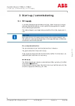
Page 29: ...gard to the oil supply please observe the engine builder s spe cifications for lubricating oil selection oil change intervals oil filtration oil pressure and oil temperature Pre and post lubrication The pre lubrication time must not be less than 5 minutes The post lubrication time is 10 minutes If the engine is allowed to idle for 10 minutes before it is shut down no additional post lubrication is...

Page 30: ... tion on the turbocharger are listed below Status for operation Oil pressure bar Admissible for normal operation 1 0 2 5 Admissible during engine warm up 1 0 5 0 Temporarily admissible 1 h alarm 0 8 1 0 Not admissible emergency stop 0 0 0 8 Admissible during pre lubrication and post lub rication engine stopped 0 2 2 5 Oil orifice A metering orifice is installed in the oil inlet of the turbocharger...

Page 31: ...art preheat oil 30 Lubricating oil temperature at the outlet The oil temperature at the outlet is mainly dependant on Lubricating oil temperature and pressure at the oil inlet Engine load and turbocharger speed Exhaust gas temperature The maximum admissible oil temperature at the outlet is listed in the fol lowing table The specified oil outlet temperature is to be considered as alarm value for th...

Page 32: ...ON Contaminated oil Particles of dirt and solid matter in the oil can cause serious damage to the machine or property u During initial commissioning and after all service work the complete lubricating system must be flushed thoroughly with warm oil u When running in the engine and after all service work on the lubricat ing system special running in filters must be used u Check oil pressure in oil ...

Page 33: ... gas temperature in front of and behind turbine u Measure air temperature in front of and behind compressor The measured values must be compared with the values in the accept ance test report while taking different operating conditions into ac count NOTICE Lubricants and pastes used during assembly of the turbocharger li quefy or vaporise and might escape as an oily liquid in the first few hours a...

Page 34: ...ir duct before gas inlet and after gas outlet u Inspect exhaust gas duct line in front of and after turbine for any combustion deposits foreign matter or residual water Clean and re move u Inspect air supply line or filter silencer for any foreign matter Clean and remove u Start up turbocharger oil circulation system at engine end u Prepare turbocharger for operation as instructed in section Inspe...

Page 35: ...bocharger The highest sound pressure level of emissions1 reaches a maximum of 105 dB A near the filter silencer and over the entire speed range The following prerequisites must be fulfilled on the turbocharger in or der to observe this limit value Fitted air inlet system All standard noise reducing measures have been taken2 The bellows at the air outlet have been perfectly insulated acoustic ally ...

Page 36: ...opyright 2018 All rights reserved HZTL2490_EN Revision D May 2018 Suggestion for noise insulation of the bellows 01 Compressor casing 04 Insulation pads 02 Bellows 05 Insulation mat at least 15 mm 03 Charge air duct scavenging air line 06 Sheet metal cover Page 34 79 ...

Page 37: ...rtened service intervals Despite observance of the service intervals unusual loads such as sev eral start stops a day harsh environmental factors poor fuel quality or heavy installation vibration can lead to premature machine damage u A shortened service interval must be arranged with ABB Turbo Sys tems NOTICE Service inspection after 5 years To prevent age and stoppage related machine damage an i...

Page 38: ...charger speed Pressure loss in air filter 4 2 3 Servicing work according to the engine manufacturer s instructions Oil filter u Clean or replace oil filter in supply line to turbocharger when engine is not running 4 2 4 Service work every 24000 36000 hours The replacement of bearing parts and the inspection and assessment of the rotor must be carried out by an ABB Turbocharging Service Station u D...

Page 39: ...s for non rotating components and bearing parts are extremely dependent upon system specific operating conditions see Influencing parameters When the specified periodic inspections are carried out the individual components are inspected for wear and tear and replaced if necessary In this way trouble free operation is ensured Influencing parameters The following parameters influence the replacement...

Page 40: ...vice hours h Gas inlet casing 50000 100000 Gas outlet casing 50000 100000 Nozzle ring 35000 75000 Turbine diffuser cover ring 35000 75000 Other casings 100000 Axial bearing components 24000 36000 Radial bearing components 24000 36000 Recommended replace ment intervals h Rotor components See rating plate information NOTICE The specified values are guides and not guaranteed See Influencing parameter...

Page 41: ...ng system permits continuous monitoring of the tur bocharger speed CAUTION Do not use cables as a climbing aid If you pull the speed measurement cables too hard contacts can be pulled out u Do not tension the speed measurement cables Part number Description 42047 Screw plug 86505 Speed sensor 86515 Cable connector for 86505 86526 F I converter 86528 Tachometer Page 39 79 ...

Page 42: ...tinuously engine performance must be reduced further u Measure the temperatures in the air and gas lines to and from the tur bochargers and compare them with standard values If the engine can be stopped for a short time u Inspect the air and gas lines as well as the turbocharger and eliminate any problems u In any event it is recommended that you contact the nearest ABB Tur bocharging Service Stat...

Page 43: ...t thermal hazards u Reduce engine performance to the idling speed then stop the engine u Switch off the lubricating oil supply to the turbocharger u Disconnect the cable connector from the speed sensor u Screw out defective speed sensor u Screw in a new speed sensor to the stop u Observe the tightening torque see the table of tightening torques in the chapter entitled Disassembly and assembly NOTI...

Page 44: ...suring system Possible reasons for failure of the speed measuring system are de scribed in the chapter Troubleshooting 4 5 Stopping the engine CAUTION Stopping the engine Heat in the turbocharger must be dissipated by the further circulating lubricating oil u Allow the engine to continue running at idling speed for a further 10 minutes before stopping Page 42 79 ...

Page 45: ...involves regular visual checks and cleaning to ensure trouble free functioning of the turbocharger and the units moun ted on it The external condition and how dirty the cleaning points given in this chapter are must be established by visual checks at the specified in tervals Observe the safety instructions during all maintenance work The cleaning point described in the following is Filter silencer...

Page 46: ...band 81005 Screw plug 81271 Lock 81006 Gasket 81136 Absorption segment 81135 Filter silencer body 81137 Sheet metal covering A Ribs E Insert unit absorption segment sheet metal covering fitted Removing and cleaning the filter silencer If provided u Remove filter ring 81265 u Rinse the filter ring 81265 using water with detergent additive or if it is heavily contaminated soak it and carefully squee...

Page 47: ...that the absorption segments 81136 are only cleaned lightly with compressed air a soft brush or with moist cleaning cloths Otherwise segments may be damaged or lose their shape NOTICE Replace absorption segments which are heavily contaminated and the filter ring with original parts from ABB Fitting the filter silencer u Assemble the insert units E by inserting the absorption seg ments 81136 into t...

Page 48: ...Rotor unbalance Contact an ABB Turbocharging Service Station Damaged turbine or com pressor Damaged bearing Rubbing of rotating parts Normal behaviour no malfunction Turbochar ger Minor uniform wear around the periphery of rotor components caused by slight local rubbing of adjacent components is per missible The compressor blades and turbine blades are then shortened somewhat Certain tolerances mu...

Page 49: ...surging Possible damage to components such as the compressor wheel tur bine blades bearings and filter silencer u Have the cause clarified immediately by an ABB Turbocharging ser vice station and rectified u Have components inspected for damage and if necessary replaced by an ABB Turbocharging service station Sporadic surge blows Surging of the turbocharger can occur during certain operating condi...

Page 50: ...ger Rotor axial clearance too large Contact an ABB Turbocharging Service Station Reduction in speed Possible causes Elimination Engine Defects of connected cylinders when pulse charging Contact the enginebuilder Turbochar ger Heavy contamination of the turbine Clean it Damaged rotor components or bearing Contact an ABB Turbocharging Service Station Pipes Defects such as leaks in the ex haust gas p...

Page 51: ...ation for example filter silencer clogged with dirt Clean it Compressor turbine con taminated Exhaust counterpressure too high Clean or repair the boiler or ex haust silencer Enlarged flow cross section of the nozzle ring due to de formed blade trailing edges Contact an ABB Turbocharging Service Station Damaged or eroded turbine Charge air cooler Cooler contaminated Clean it Cooling water volume t...

Page 52: ...an it Compressor turbine contam inated Damaged compressor tur bine Contact an ABB Turbocharging Service Station Exhaust counterpressure too high Clean or repair the boiler or ex haust silencer Charge air pressure too high Engine performance and engine speed unchanged air intake condition normal Possible causes Elimination Engine Malfunctioning injection sys tem Repair it or contact the manu factur...

Page 53: ...ing disc increases As a result the voltage amplitude of the speed signal decreases which can cause prob lems for the evaluation electronics This problem is eliminated by removing the gasket Defective sensor Contact ABB Turbocharging service sta tion Measured speeds too high Dirty sensor tip The sensor tip is magnetic and can thus at tract metal particles As a result the dis tance to the auxiliary ...

Page 54: ...rating plate depending on the specification Weight kg TPR56 F TPR61 F 360 700 7 2 Removing the turbocharger u Disconnect all gas air and oil pipes in accordance with the engineb uilder s instructions CAUTION Oil orifice plates An orifice plate for adjusting the oil pressure is fitted in each of the two oil inlet channels in the bearing casing When the cartridge group the bearing casing or the turb...

Page 55: ...Loosen the fixing screws 01 at the foot u Remove the sliding blocks 02 u Lift the turbocharger off the engine and set it down to one side WARNING Beware of tilting If support for the turbocharger is not provided or is inadequate the turbocharger could tip over during installation or removal and cause a serious or even fatal injury u Wear personal protective equipment PPE u Support the turbocharger...

Page 56: ...ce with the cor rect diameter is installed in the oil feeding oil inlet channel u Reuse the same orifice that was installed before Tightening torques for fixing screw 01 TPR56 F TPR61 F 135 Nm 205 Nm u Inspect the lifting gear u Attach one lifting gear each to the two fins of the bearing casing provided for this purpose u Align turbocharger on bracket u Fit the sliding blocks 02 u Tighten the inne...

Page 57: ...This list is enclosed in the toolbox WARNING Maintaining assembly devices Assembly devices must be checked for damage before and after use u Visually check for corrosion cracks deformation and wear u Don t use damaged assembly devices but replace them Customer spare parts set Before beginning work ensure that the required customer spare parts sets are available u See chapter Spare parts Tightening...

Page 58: ...perly on the crane hook u Do not let anyone stand beneath a suspended load Wear safety gloves to protect against mechanical hazards Wear safety helmet Definition of terms Suspension point Defined load attachment point on a component or an assembly blind hole thread eye lug Assembly device Devices that are fitted on the turbocharger in order to obtain a sus pension point Assembly devices are specia...

Page 59: ...s are guides roun ded off to the next highest value Weights kg Item Description TPR56 F TPR61 F 1 Filter silencer 65 2 Radial air suction branch 16 35 3 Axial air suction branch 10 16 4 Compressor casing 95 145 5 Wall insert 22 45 6 Diffuser 7 11 7 Cartridge group 100 160 8 Turbine diffuser 13 20 9 Gas outlet casing 130 180 10 Nozzle ring 3 7 11 Axial gas inlet casing 16 21 12 Radial gas inlet cas...

Page 60: ...user and the wall insert 8 3 Removing and installing the air suction branch filter silencer Removing the air suction branch u Disconnect all pipes ducts in accordance with the enginebuilder s in structions u Loop lifting gear around air suction branch Lifting gear may be passed through any holes provided in ribs to improve stability u Unscrew nuts 72027 and remove them together with washers 72018 ...

Page 61: ...0_EN Revision D May 2018 Removing filter silencer u Disconnect all air lines in accordance with engine builder s instruc tions u Loop lifting gear around filter silencer 81000 u Unscrew nuts 72027 and remove them together with washers 72018 u Remove filter silencer and it set down to one side Fitting the filter silencer u Fit filter silencer in reverse order Page 59 79 ...

Page 62: ...Wear safety gloves to protect against mechanical hazards w The axial clearance A must be measured after the cartridge group has been removed and before it is fitted u Measure and note the axial clearance A Clearance A mm TPR56 F TPR61 F 0 21 0 37 0 24 0 40 CAUTION Clearances out of tolerance Clearances out of tolerance and excessively worn components can be the cause of serious damage to machinery...

Page 63: ...roup the bearing casing or the turbocharger is fitted to the engine it must be ensured that the orifice plates that are specified for the turbocharger have been installed in the two oil inlet channels u Check correct installation of oil orifice plates 8 5 1 Removing the compressor casing u Remove three studs 72029 at top u Attach lifting device 90190 to compressor casing 72000 then fasten and secu...

Page 64: ...ate the compressor casing and set it down on an underlay NOTICE Ensure that the underlay does not shift u Make certain that the compressor casing rests only on the flange F u Check underlay and adjust if necessary u Remove the screw 72002 u Remove the diffuser 79000 u Pull out and remove the wall insert 77000 using a swivel lifting eye 90230 and plug bolt 90865 u Remove O rings 77005 77006 Page 62...

Page 65: ...u Remove screw 61059 with Verbus Ripp washers 61058 and two nuts 61064 u Attach one lifting gear each to the two fins of the bearing casing provided for this purpose u Evenly press off cartridge group by screwing press off screws 90900 into the designated holes CAUTION If the blades on the rotor have insufficient or no clearance this might cause damage to the blades and the casing u Check that the...

Page 66: ...4 and also remove possible contamination behind the flange u Cover the oil connections CAUTION Further operations This Operation Manual may be used to carry out only those operations that are described in it Erroneous disassembly and assembly of the cartridge group can lead to serious damage to the machine u ABB Turbo Systems recommends having further operations carried out only by trained personn...

Page 67: ..._EN Revision D May 2018 8 6 Dismantling and installing the turbine diffuser and nozzle ring u Position clamp 90921 over stud 61036 until it lies flat against inner radius of gas outlet casing u Insert extension A of torque spanner B through clamp hole and only loosen screws 61056 one after other u Do not remove the screws 61056 and Verbus Ripp washers 61057 yet Page 65 79 ...

Page 68: ...d threads 61036 u Remove the remaining screws 61056 and Verbus Ripp washers 61057 u Press the turbine diffuser 63000 free using the press off screws 90901 and pull it out it until the clamp 90921 is up against the nut 61037 u Remove the nut 61037 and clamps 90921 from the stud u Fully withdraw the turbine diffuser and remove it u Remove the guide studs 90320 u Pull nozzle ring 56001 forward and re...

Page 69: ...ine it must be ensured that the orifice plates that are specified for the turbocharger have been installed in the two oil inlet channels u Check correct installation of oil orifice plates CAUTION If there is no or insufficient clearance between the rotor turbine blades and the turbine diffuser the blades and the turbine diffuser casing can be damaged u Remove the cover from the oil connection u Fi...

Page 70: ... complete with its O ring 86506 and plug in the cable connector 86515 u Fit O ring 42012 8 7 1 Fitting compressor casing u Fit O rings 77005 77006 u Fit lifting gear swivel lifting eye 90230 and plug bolt 90865 u Align the wall insert 77000 to the threaded holes in the compressor casing 72000 using the lugs on the swivel lifting eyes then lower it u Fit the diffuser 79000 u Screw in the screw 7200...

Page 71: ...u Push compressor casing 72000 fully onto cartridge group and se cure using nuts 61037 u Secure three press off nuts 61090 against compressor cas ing 72000 by tightening them to specified torque see chapter Table of tightening torques u Remove lifting device 90190 u Measure and note the axial clearance A see the section on axial clearance CAUTION If the axial clearance A is out of tolerance an ABB...

Page 72: ...Operation Manual TPR56 F TPR61 F 8 Disassembly and assembly 8 8 Table of tightening torques Copyright 2018 All rights reserved HZTL2490_EN Revision D May 2018 8 8 Table of tightening torques Page 70 79 ...

Page 73: ...90_EN Revision D May 2018 Tightening torques Nm Item Part number TPR56 F TPR61 F 1 72027 M10 30 M12 50 2 61036 72026 M10 20 M12 30 3 72002 M6 10 M8 25 4 61044 61056 61059 M10 80 M12 130 5 61064 M10 35 M12 60 6 42059 42064 M10 80 M12 130 7 86505 If provided M18x1 5 150 M18x1 5 150 8 61037 M10 50 M12 80 9 61090 M10 10 M12 10 Page 71 79 ...

Page 74: ...and this is circulated by the pre lubrica tion pump no measures have to be taken Any remaining old engine oil will therefore be flushed away and the bearing sections largely protected against corrosion Mothballing measures WARNING Handling operating materials and supplies Swallowing or inhaling vapours of operating materials and supplies or contact with them may be harmful to health u Do not breat...

Page 75: ...taking an engine out of opera tion u Dismantle the turbocharger u The rotor and the bearing parts must be removed by an official ABB Turbocharging service station and refitted afterwards u Clean all parts u Machined bright surfaces of steel and cast parts must be oiled with anticorrosive oil u Reassemble complete turbocharger Rotor turning in stack draught If the rotor turns as a result of the sta...

Page 76: ...vidual parts See the section Taking out of operation for up to 12 months under Mothballing measures for the measures always necessary when moth balling turbocharger parts If the turbocharger remains mounted on the engine refer to the section Taking out of operation for up to 12 months under Rotor turning in stack draught If the entire turbocharger is removed or if the turbocharger is re as sembled...

Page 77: ...spiratory mask to protect against dusts Wear safety gloves to protect against mechanical hazards Disposal must be environmentally compatible professional and in com pliance with locally applicable regulations The turbocharger consists largely of metal cast iron materials steel nickel steel alloys aluminium and bearing brass Further components are Non metallic materials filter components of felt an...

Page 78: ... into consideration in this document please contact an ABB Turbocharging service station CAUTION Storage of spare parts All spare parts ordered with the turbocharger must be kept complete and ready for use u Parts showing signs of rust should be carefully cleaned and greased u Dispose of replaced and unusable parts in a professional and environ mentally compatible way Required customer spare part ...

Page 79: ...Operation Manual TPR56 F TPR61 F 11 Spare parts 11 1 Ordering spare parts Copyright 2018 All rights reserved HZTL2490_EN Revision D May 2018 Page 77 79 ...

Page 80: ...ion Manual TPR56 F TPR61 F 11 Spare parts 11 2 View of turbocharger with part numbers Copyright 2018 All rights reserved HZTL2490_EN Revision D May 2018 11 2 View of turbocharger with part numbers Page 78 79 ...

Page 81: ... spare part set Verbus Ripp washer 61044 in customer spare part set Hexagon head screw 61056 in customer spare part set Hexagon head screw 61057 in customer spare part set Verbus Ripp washer 61058 in customer spare part set Verbus Ripp washer 61059 in customer spare part set Hexagon head screw 63000 Turbine diffuser 72000 Compressor casing 72018 Washer 72027 Hexagon nut 77000 Wall insert 77005 in ...

Page 82: ...ABB Turbo Systems AG Bruggerstrasse 71a CH 5400 Baden Switzerland ABB ...

Reviews: