background image

2  TRIO 20.0/27.6-TL-OUTD-US-480 | Programming for HECO compliance

1. Introduction

This instruction provides the method to reprogram the ABB TRIO-20.0/27.6-TL-OUTD-X-US-480 to the Hawaii Electric Company, 
Inc. (HECO) ultra-fast trip transient over-voltage requirements (TrOV-2) and frequency voltage ride through (FVRT) mitigation 
requirements as described in the document “Appendix IIA Full Ride Through Settings for O’ahu, Maui, Hawai’i” dated January, 
2015. Details of these requirements are available on the HECO website at: http://www.hawaiianelectric.com/vcmcontent/
StaticFiles/pdf/TrOVandFVRT_Public_Feb2015.pdf.

Every operation performed on the TRIO-20.0/27.6-TL-OUTD-X-US-480 shown in this instruction must be 
performed following existing regulations and safety instructions and carried out in compliance with the 
instructions provided in the product manual located at http://www.abb.com/solarinverters/.

2. Parameter setting via inverter’s display 

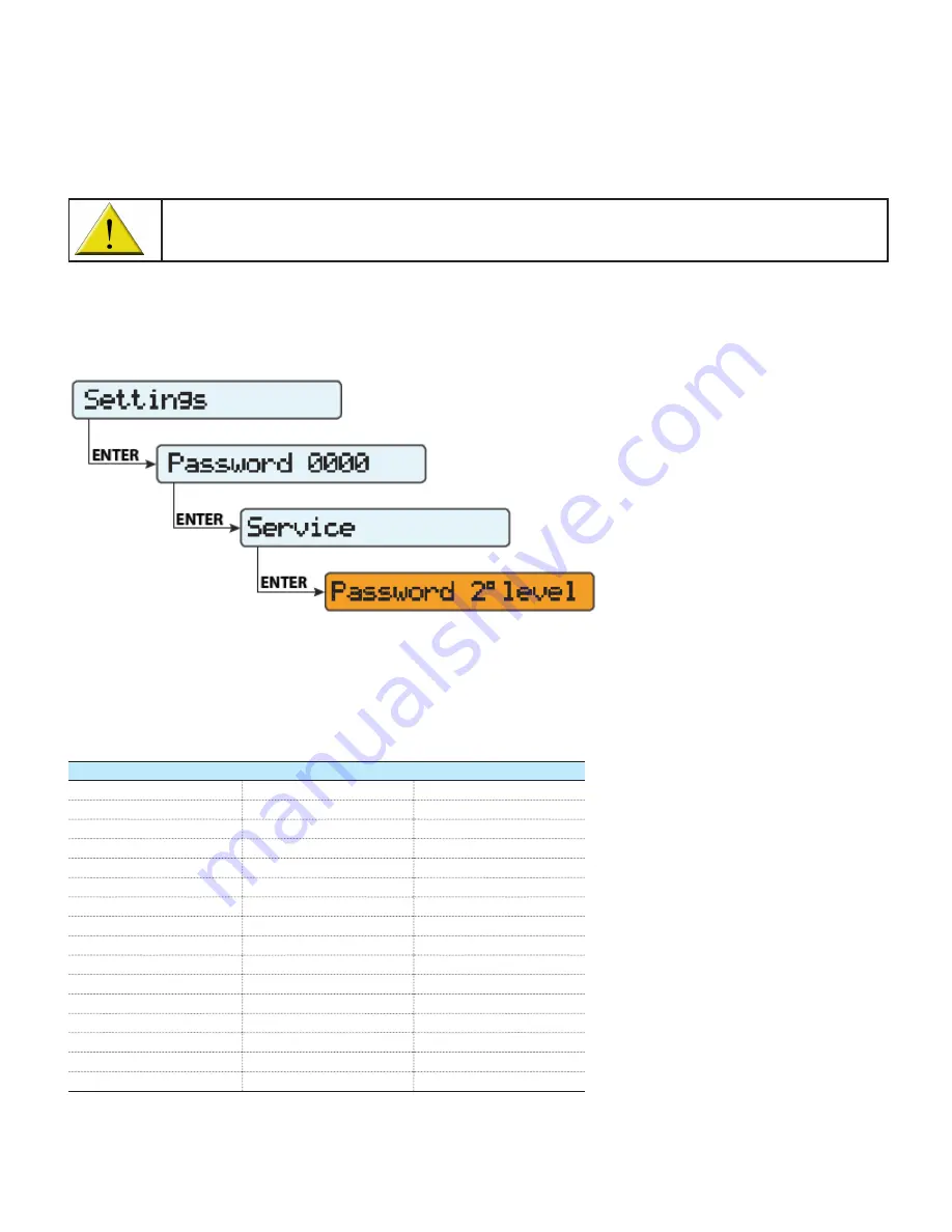
HECO requirement settings can be set via the TRIO’s LCD display using the service menu (accessible using the buttons on the 
inverter’s LCD panel) as shown in Figure 1 below. Note: to obtain the second level password, call ABB solar inverter post-sales 
technical support at 1-877-261-1374, 6 a.m. - 6 p.m. MST.

After entering the second level password, the list of inverter grid parameters can be accessed using the UP and DOWN buttons. 
Once the parameter indicated in the center column (Inverter parameter) of Table 1 below is highlighted, press ENTER. Then, use 
the UP/DOWN buttons to increase or decrease the parameter’s value. Select the new setting value shown in the right column. 
Once all settings have been changed, press ENTER to confirm.

HECO parameter

Inverter parameter

Setting value

OVR2

Set U>>

332.5V

UVR2

Set U<<

138.5V

OFR2

Set F>>

64Hz

UFR2

Set F<<

56Hz

OVR1

Set U>

304.7V

UVR1

Set U<

243.V

OFR1

Set F>

63Hz

UFR1

Set F<

57Hz

OVR2

Set time U>>

160ms (default value)

UVR2

Set time U<<

160ms (default value)

OFR2

Set time F>>

160ms (default value)

UFR2

Set time F<<

160ms (default value)

UVR1

Set time U<

20s

OVR1

Set time U>

920ms

OFR1

Set time F>

20s

UFR1

Set time F<

20s

Figure 1 - Service menu

Table 1 - inverter grid parameters and associated HECO settings

Summary of Contents for TRIO-20.0-TL-OUTD-X-US-480

Page 1: ... 2 3 Parameter setting via software tool Aurora Manager Lite 3 Appendix A How to connect the laptop PC to the inverter 6 Appendix B How to launch Aurora Manager LITE 7 Contents ABB solar inverters Programming for HECO compliance TRIO 20 0 27 6 TL OUTD X US 480 ...

Page 2: ...he TRIO s LCD display using the service menu accessible using the buttons on the inverter s LCD panel as shown in Figure 1 below Note to obtain the second level password call ABB solar inverter post sales technical support at 1 877 261 1374 6 a m 6 p m MST After entering the second level password the list of inverter grid parameters can be accessed using the UP and DOWN buttons Once the parameter ...

Page 3: ...x A How to connect the laptop PC to the inverter on page 6 of this instruction For the procedure to access the Aurora Manager Lite software refer to Appendix B How to launch Aurora Manager LITE on page 7 of this instruction When multiple TRIO inverters are daisy chained it is possible to change the parameters on all inverters connected in the chain at one time Once the laptop PC is connected to th...

Page 4: ... Figure 3 below Voltage and Frequency grid parameters are all now accessible To set the HECO parameters outlined in Table 1 on page 2 of this instruction the boxes in the New columns must be changed as shown in Figure 4 below Figure 3 Click on the AC side tab then the Grid protection tab Figure 4 Change information in the New columns ...

Page 5: ... 5 Rather than changing the settings for each individual TRIO inverter in a daisy chain configuration select Apply setup changes to ALL connected units at the top of the screen as shown in Figure 5 below Figure 5 Apply setup changes changes to ALL connected units ...

Page 6: ...e performed Switch OFF the inverter using the DC disconnect Remove the wiring box cover by unscrewing the six 6 lateral screws Remove the mylar cover on the communication board Connect the RS485 cables on the PC SERV port see top blue rectangle box in Figure 6 above using an RJ45 plug or the terminal block see bottom blue rectangle box in Figure 6 above by wiring the GND COM PC T R and PC T R as s...

Page 7: ...s connected to a laptop PC as described in Appendix A access the COM settings as shown in Figure 8 below To determine which COM port to use once the inverter is connected to the laptop PC through the adapter this can be determined by opening the computer s Control Panel and clicking on the Device Manager tab and then on the Ports COM LPT tab as shown in Figure 9 below Figure 8 Launch Aurora Manage...

Page 8: ...remains 19200 See Figure 10 below By clicking on Apply and then OK the COM settings are confirmed At this point on the main screen it is possible to scan for inverters connected to the laptop PC as shown in Figure 11 below Once the inverter s are found select an inverter and additional TAB selections will appear as shown in Figure 12 Figure 10 List of active COM ports Figure 11 Scan for inverters ...

Page 9: ...upport and then clicking OK to confirm New features will be available in the software Press the REFRESH button and click on any inverter icon in the list and new TABs will then appear as shown in Figure 15 below These new tabs are available for all inverters listed and are to be used to change the iinverter parameters as discussed in section 3 Parameter setting via software tool Aurora Manager Lit...

Page 10: ...EN BCM 00362 0AP_REV AA 24 JuLY 2015 For more information please contact www abb com solarinverters Copyright 2015 ABB All rights reserved Specifications subject to change without notice ...

Reviews: