Vortex Meter (TRIO-WIRL V) 3 - 10
PN25080
TRIO-WIRL INSTRUCTION MANUAL
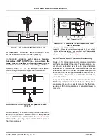
FLOWMETER PRIMARY INSTALLATIONS FOR
FLUID TEMPERATURES > 300
o
F (150° C)
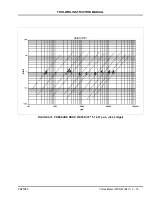
In horizontal installations,
when process tempera-
tures above 300
o
F (150
o
C) are encountered, the
meter must be oriented so that the junction box is
located to the side or below meter body, not above.
Refer to Figure
for an example of the recom-
mended high-temperature application orientation.
.
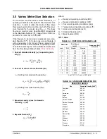
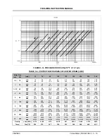
When operating at elevated temperatures, the interre-
lationship between the fluid and ambient temperatures
must be taken into consideration. Figure
shows
the allowable operating range for ambient vs. process
fluid temperatures.
1) Cables suitable 230
o
F (110°C) can be used for the power supply
terminals 31, 32 and the contact output terminals 41, 42 without any
reduction in the temperature range specifications. Cables suitable
only for temperatures of 175
o
F (80°C) reduce the temperature range
of the flowmeter as shown in Figure
3.4.3 Temperature/Pressure Monitoring
Provisions for temperature and/or pressure monitoring
are the responsibility of the user. The temperature sen-
sor should be located five to eight pipe diameters
downstream of the flowmeter. Measurement is from the
downstream face of the meter. The pressure tap should
be located three to five pipe diameters downstream of
the flowmeter. Measurement is from the downstream
face of the meter.
An option is available for the vortex meter for direct
Pt100 temperature measurements. These temperature
measurements can be used to monitor the fluid tem-
perature or for the measurement of saturated steam in
mass units.
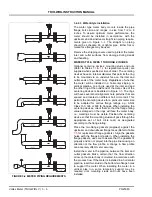
FIGURE 3-11 INSULATING THE PIPELINE
FIGURE 3-12 Orientation for Temperatures >300° F
(150
o
C)
Fluid Temperature [°C]
Ambien
t T
emp
eratur
e [
o
C]
1)
Allowable
Temperature Range
HT-Design
≤
400°C
for Std. Design
(
≤
280°C)
Side View, Pipeline
Installation for
Fluid Temperatures > 150°C
-20
FIGURE 3-13 AMBIENT/FLUID TEMPERATURE
RELATIONSHIP


